 View in your room · AR
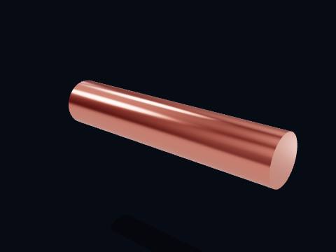
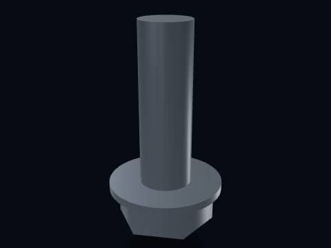
Pump shaft
The pump shaft, driven directly by the motor through a flexible coupling. It carries no reduction — whatever speed the motor turns at, the impeller turns at exactly the same speed.
More about this part
- Material: Steel
- Diameter: Ø 30 mm
Free 3D model · STL · GLB · AR
By Parth Parmar, mechanical design engineer · 31 pieces, 20 parts · Updated
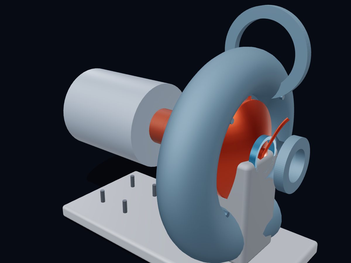
A centrifugal pump moves liquid with a spinning impeller. Liquid enters the centre of the impeller (the eye), the vanes throw it outward at high speed, and the spiral volute casing around the impeller slows that fast flow down, turning its speed into pressure that pushes the liquid out of the discharge.
 Open full screen →
Live 3D: drag to turn it, pinch to zoom, explode it, cut it open, X‑ray it and watch it run. Free, in your browser, no app. Open it full screen →
Single parts: scroll to the parts list. These are learning models, not a print kit: some parts touch or overlap and there are no fit tolerances.
Free for personal and educational use under CC BY-NC 4.0. Credit “Engine-X by Parth Parmar (engx3d.com)” when you share or remix it. Don’t sell the files or prints. For commercial use, get in touch. Every file carries the Engine-X mark and a hidden digital fingerprint that identifies it.
| Machine | Single-stage end-suction · Ø164 mm impeller · 6 backward-curved vanes |
|---|---|
| Parts modeled | 31 named parts in 5 systems (20 different parts to download) |
| Model size | 425 × 396 × 302 mm (real scale) |
| Formats | GLB (glTF 2.0) 2.1 MB, STL 1.5 MB, USDZ for iPhone AR, ZIP of part STLs 0.3 MB |
| Live 3D | Engine‑X atlas: true motion, explode, section, X‑ray |
| License | CC BY-NC 4.0, free with credit |
| Rotating group | 6 parts: Shaft, coupling, impeller (hub, shroud and blades) and the rotating seal ring. |
|---|---|
| Bearing housing | 5 parts: Bearing housing, both bearings, and the stationary half of the mechanical seal. |
| Volute casing | 5 parts: Cast casing, suction and discharge flanges, wear ring and casing bolts. |
| Frame & motor | 3 parts: Baseplate, casing foot and the drive motor. |
| Hardware | 1 parts: Motor mounting bolts. |
Every part with a picture, what it does and its own STL file: pump shaft, flexible coupling, mechanical seal (rotating ring), impeller hub, impeller front shroud, impeller blade, bearing housing, bearing (inboard) and more. Open any part in the live 3D atlas to see where it sits and how it moves. A part used several times (valves, bolts) is shown once with its count.
↓ Download all parts · ZIP · 0.3 MB
Shaft, coupling, impeller (hub, shroud and blades) and the rotating seal ring.
The pump shaft, driven directly by the motor through a flexible coupling. It carries no reduction — whatever speed the motor turns at, the impeller turns at exactly the same speed.
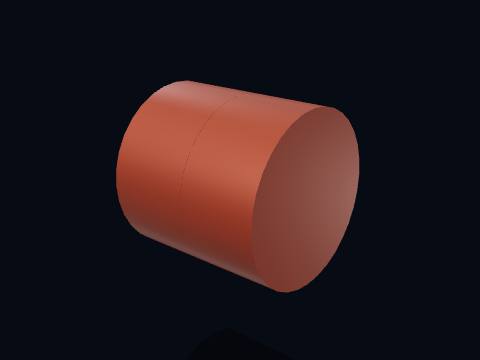
A flexible coupling joining the motor shaft to the pump shaft. Its elastomer insert absorbs minor misalignment and cushions torque spikes while still transmitting rotation at a fixed 1:1 ratio.

The rotating half of the mechanical seal, spring-loaded against the stationary seat behind it. Together the two lapped faces — one spinning, one fixed — stop pressurized liquid from leaking out along the shaft, the classic failure point of any pump.
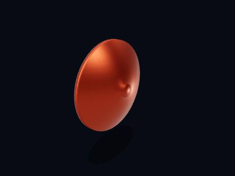
The impeller's back plate (hub). It carries the blades and keys onto the shaft; its curved profile smooths the flow as liquid turns from axial (entering the eye) to radial (leaving at the tip).

The impeller's front shroud, closing the blade passages on the inlet side except for the central eye. A shrouded (closed) impeller like this one runs more efficiently than an open one, at the cost of being harder to clear if it clogs.

One of 6 backward-curved vanes. Backward curvature — the blade leans away from the direction of rotation at the tip — gives the flattest, most stable head-flow curve of any impeller shape, which is why it's the default choice for a general-purpose pump.
Bearing housing, both bearings, and the stationary half of the mechanical seal.
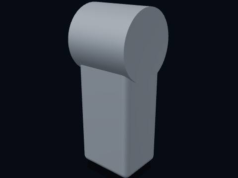
The bearing housing (bracket), bolted to the baseplate. It carries the shaft's radial and axial loads through a pair of ball bearings, well clear of the wet end.
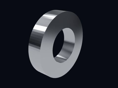
A deep-groove ball bearing, shown simplified as its outer race. It lets the shaft spin freely while carrying the impeller's side loads and the pump's axial thrust back to the housing.
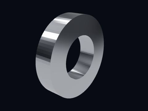
A deep-groove ball bearing, shown simplified as its outer race. It lets the shaft spin freely while carrying the impeller's side loads and the pump's axial thrust back to the housing.

The stationary half of the mechanical seal: a hard, flat-lapped face that the rotating carbon ring rides against. Both faces are lapped flat to within a fraction of a micron.
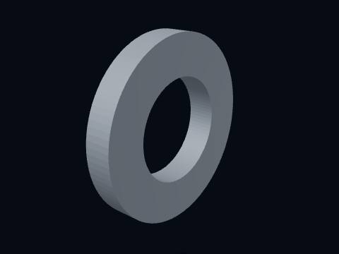
The seal gland (stuffing-box cover), which holds the stationary seal seat square to the shaft and bolts the whole seal cartridge to the casing.
Cast casing, suction and discharge flanges, wear ring and casing bolts.
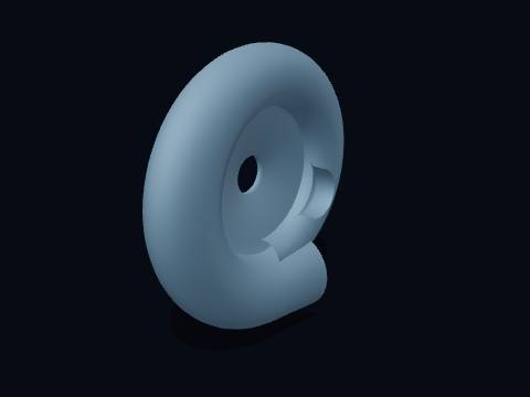
The volute casing. Liquid leaves the impeller at high velocity and low pressure; the volute's cross-section grows steadily as it wraps around the impeller, so the flow slows down and its velocity head converts into pressure head — the same principle as a diffuser — on the way to the outlet.
Cast in one piece with the suction nose; the back is closed by the bearing-housing side of the assembly.

The suction flange, bolted to the inlet pipework. Its bore lines up with the impeller eye so incoming liquid arrives with as little swirl and turbulence as possible.

The discharge flange, at the end of the volute's spiral. By the time liquid reaches here most of its velocity head has already been converted to pressure head.

A replaceable wear ring, closing the small clearance gap between the impeller eye and the casing. It's designed to wear out (and be swapped) instead of the far more expensive impeller or casing wearing out of round.
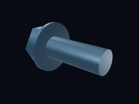
A casing joint bolt, clamping the suction cover to the volute body against full discharge pressure.
Baseplate, casing foot and the drive motor.
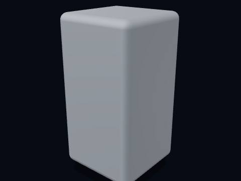
A support foot, carrying the casing's weight and the pipework's reaction loads down to the baseplate.
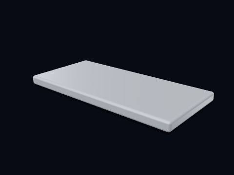
The baseplate. It holds the pump and motor in fixed alignment — misalignment here is one of the most common real-world causes of bearing and seal failures.
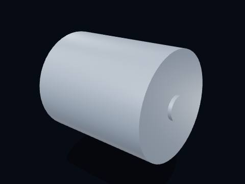
The driver: a flange- or foot-mounted electric motor, coupled directly to the pump shaft with no speed reduction in between.
Motor mounting bolts.
How does it work? Read the step-by-step guide, with key facts and common questions.
How a centrifugal pump works →Yes. The centrifugal pump 3D model is free for personal and educational use under CC BY-NC 4.0: credit "Engine-X by Parth Parmar (engx3d.com)". Selling the files or prints, or other commercial use, needs written permission.
GLB (glTF 2.0) with colours and named parts, STL in millimetres (Z-up) for CAD, slicers and 3D printing, USDZ for AR on iPhone, and a ZIP with all 20 parts as separate STL files.
31 named pieces in 5 systems (rotating group, bearing housing, volute casing, frame & motor, hardware). Repeated pieces such as bolts are folded together, which leaves 20 different parts, each one downloadable on its own.
Yes, download the STL (whole machine or single parts) and open it in your slicer. It is a learning model at real scale, not a print kit: some parts touch or overlap and there are no fit tolerances, so scale it and print parts one by one.
Tap "View in your room" on this page. Android opens Google Scene Viewer and iPhone opens AR Quick Look, both without an app, and you can place the model at real size on the floor or a table.
Yes. Tap "Play live 3D here" or open the Engine-X atlas (engx3d.com/atlas#m=pump): it runs in the browser with true motion, and you can explode it, cut it open and X-ray it.
Credit line: Centrifugal pump 3D model, Engine-X by Parth Parmar (engx3d.com)
Citation: Parmar, P. (2026). Centrifugal pump 3D model [3D model, CC BY-NC 4.0]. Engine-X. https://engx3d.com/3d-models/centrifugal-pump
 TurbochargerJournal-bearing turbo · Ø60 mm compressor · internal wastegateView and download →
 Pulley & belt driveV-belt speed reducer · Ø100/Ø250 mm pulleys · 2.50 : 1View and download →
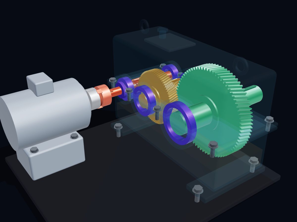 Helical gear reducerTwo-stage helical gearbox · 16 : 1 · 1440 → 90 rpmView and download →
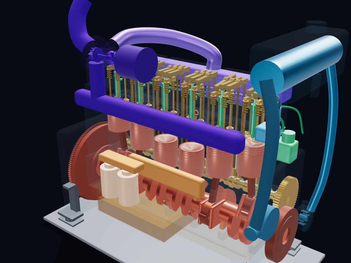 Marine diesel engineInline-6 · NT855 Big Cam style · 14 L · PT fuel systemView and download →
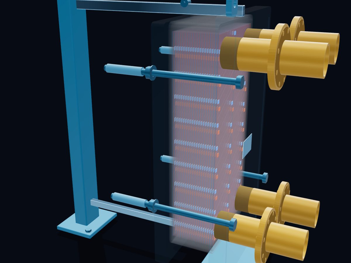 Plate heat exchangerGasketed, 41 plates · DN100 · countercurrentView and download →
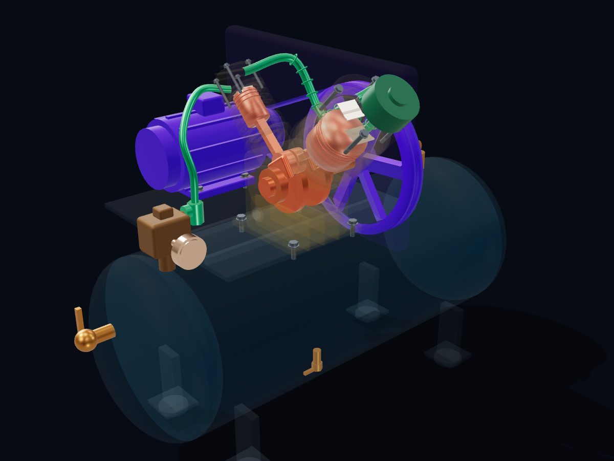 Reciprocating air compressorTwo-stage V-twin · 12 bar (175 psi) · 3.7 kWView and download →
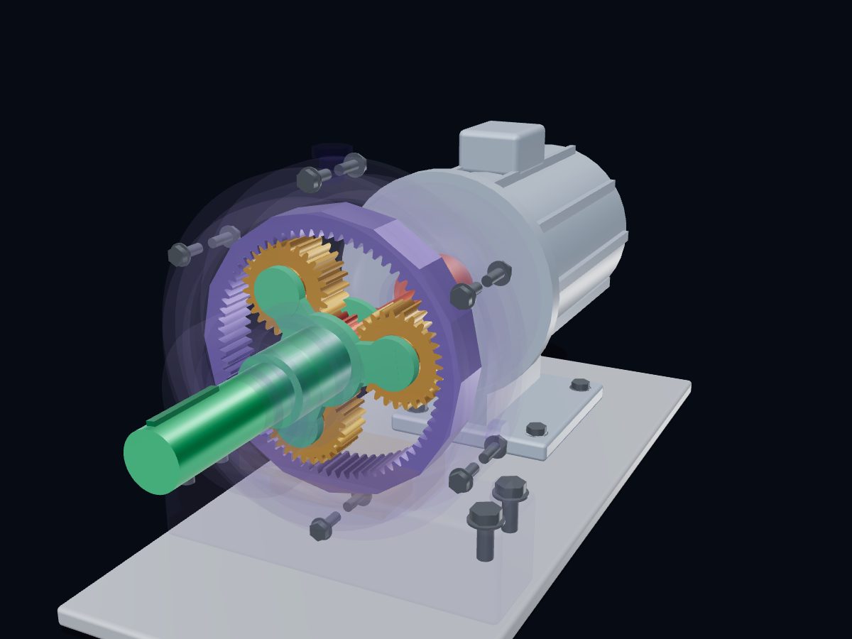 Planetary gearboxSun 18 · planets 3 × 27 · ring 72 · 5 : 1View and download →
All 3D models → · Live 3D atlas · Need an interactive 3D page for your own machine? Work with Engine‑X.