By Parth Parmar, mechanical design engineer · 61 pieces, 43 parts · Updated
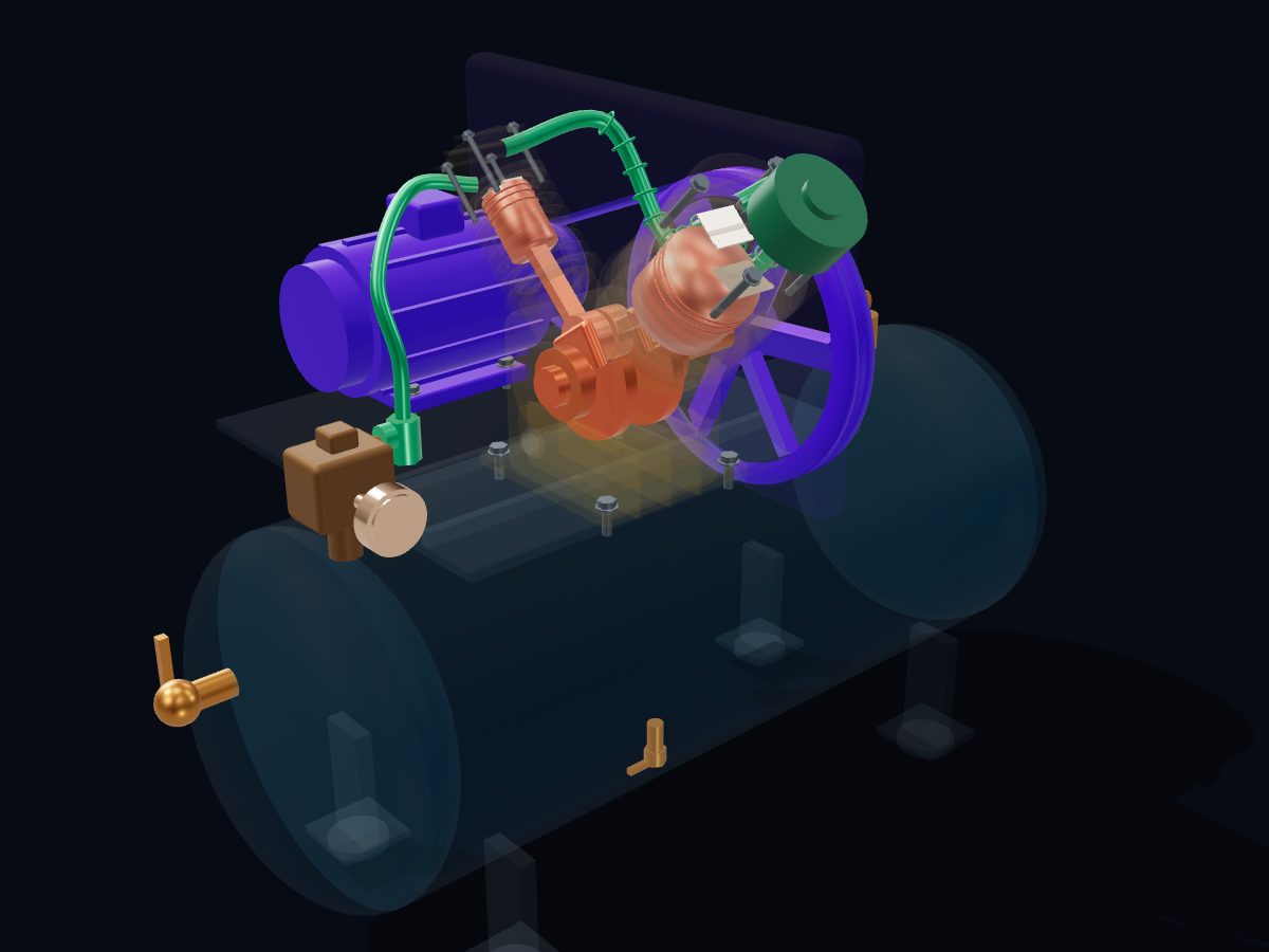
A reciprocating air compressor squeezes air with a piston in a cylinder. On the downstroke the piston draws air in through a suction valve; on the upstroke it compresses the air until the delivery valve opens and pushes it into a storage tank. Two-stage machines compress in two cylinders and cool the air in between.
Single parts: scroll to the parts list. These are learning models, not a print kit: some parts touch or overlap and there are no fit tolerances.
Free for personal and educational use under CC BY-NC 4.0. Credit “Engine-X by Parth Parmar (engx3d.com)” when you share or remix it. Don’t sell the files or prints. For commercial use, get in touch. Every file carries the Engine-X mark and a hidden digital fingerprint that identifies it.
Key facts
Machine
Two-stage V-twin · 12 bar (175 psi) · 3.7 kW
Parts modeled
61 named parts in 7 systems (43 different parts to download)
Model size
1162 × 865 × 755 mm (real scale)
Formats
GLB (glTF 2.0) 4.2 MB, STL 3.0 MB, USDZ for iPhone AR, ZIP of part STLs 0.7 MB
8 parts: Crankshaft, main bearings, two connecting rods, pistons and pins.
Cylinders & valves
13 parts: Crankcase, finned LP and HP barrels, valve plates, reed valves, heads and oil.
Air path
4 parts: Intake filter, intercooler, discharge tube and check valve.
Motor & belt drive
5 parts: Motor, motor pulley, V-belt, flywheel fan pulley and belt guard.
Air receiver
3 parts: Tank, saddle plate and feet.
Controls & safety
6 parts: Pressure switch with unloader, gauge, safety valve, service valve and drain.
Hardware
4 parts: Head bolts and mounting bolts.
All 43 parts of the reciprocating air compressor, one by one
Every part with a picture, what it does and its own STL file: crankshaft, main bearing, lp piston (ø100 mm), lp piston pin, lp connecting rod, hp piston (ø53 mm), hp piston pin, hp connecting rod and more. Open any part in the live 3D atlas to see where it sits and how it moves. A part used several times (valves, bolts) is shown once with its count.
Crankshaft, main bearings, two connecting rods, pistons and pins.
Crankshaft
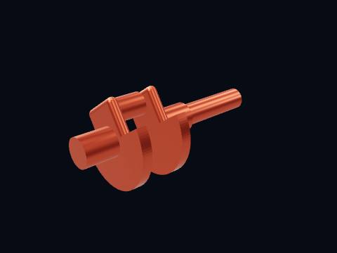
The crankshaft turns the motor's rotation into the pistons' up-and-down strokes. One crankpin carries both connecting rods side by side, so the two cylinders, set 90° apart, take their strokes a quarter turn apart. It turns at about 900 rpm, 3.2 times slower than the motor.
More about this part
The counterweight opposite the crankpin balances the rotating mass of the pin and the rod big ends.
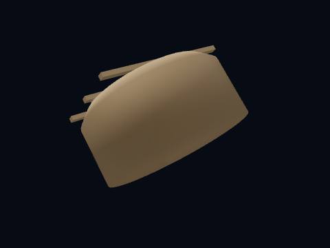
The low-pressure (first-stage) piston, 100 mm across. On its downstroke it draws in outside air through the filter; on its upstroke it squeezes that air to about 2.6 bar and pushes it into the intercooler.
More about this part
Two compression rings seal the air above; the lower oil ring scrapes oil back down the wall so little reaches the air.
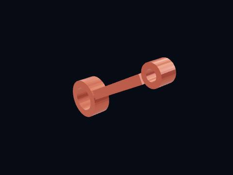
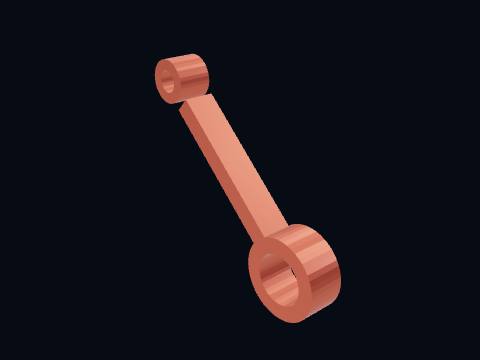
A connecting rod, 140 mm between centres, links the crankpin to a piston. It turns the crankpin's circle into the piston's straight up-and-down stroke. Both rods share one crankpin.
The high-pressure (second-stage) piston, only 53 mm across. It takes the already-compressed, cooled air from the intercooler and squeezes it again, up to 12 bar (175 psi), for the tank.
More about this part
With equal strokes, the bore ratio follows the stage pressure ratio: 53 ÷ 100 ≈ 1 ÷ √3.6.
A connecting rod, 140 mm between centres, links the crankpin to a piston. It turns the crankpin's circle into the piston's straight up-and-down stroke. Both rods share one crankpin.
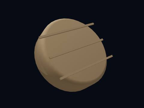
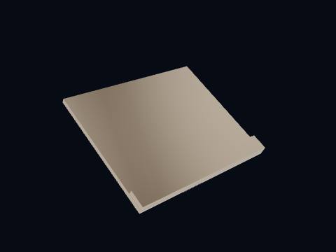
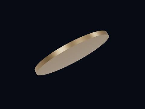
The valve plate, clamped between barrel and head. It carries the two reed valves for its cylinder: suction on the cylinder side, delivery on the head side.
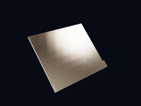
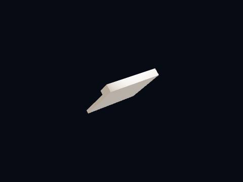
The suction (inlet) reed valve: a thin spring-steel flap. When the piston moves down and the cylinder pressure falls below the inlet pressure, the flap bends open and air rushes in; it snaps shut as soon as the piston turns round.
More about this part
It opens a little after the stroke begins, because the air trapped in the clearance space must first re-expand.
The lift is exaggerated in the model so you can see it move.
The delivery (discharge) reed valve lets compressed air out of the cylinder. It stays shut while the piston compresses the air and only opens late in the upstroke, once the cylinder pressure beats the pressure waiting beyond it.
More about this part
Worn or leaking reeds cut the air the compressor delivers; they are a routine replacement part.
The valve plate, clamped between barrel and head. It carries the two reed valves for its cylinder: suction on the cylinder side, delivery on the head side.
The high-pressure cylinder head closes the top of the small second-stage cylinder. Its inlet comes from the intercooler and its outlet goes to the discharge tube and the tank.
The suction (inlet) reed valve: a thin spring-steel flap. When the piston moves down and the cylinder pressure falls below the inlet pressure, the flap bends open and air rushes in; it snaps shut as soon as the piston turns round.
More about this part
It opens a little after the stroke begins, because the air trapped in the clearance space must first re-expand.
The lift is exaggerated in the model so you can see it move.
The delivery (discharge) reed valve lets compressed air out of the cylinder. It stays shut while the piston compresses the air and only opens late in the upstroke, once the cylinder pressure beats the pressure waiting beyond it.
More about this part
Worn or leaking reeds cut the air the compressor delivers; they are a routine replacement part.
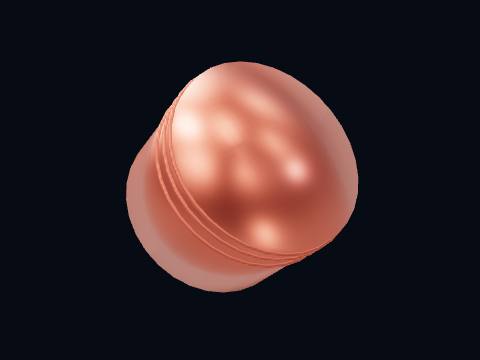
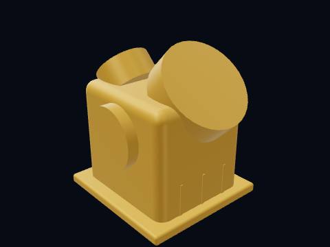
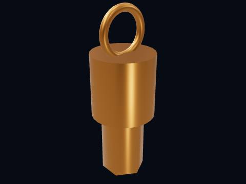
The crankcase breather and oil-fill cap lets the crankcase breathe and is where oil is topped up. It lets air in and out as the pistons move, so the crankcase does not pump itself up and push oil past the rings.
Intake filter, intercooler, discharge tube and check valve.
Intake air filter
The intake air filter cleans the air before it enters the first-stage cylinder. All the air the compressor will ever deliver enters here, so a clogged element cuts output and raises the temperature; a missing one lets dust wear the cylinder.
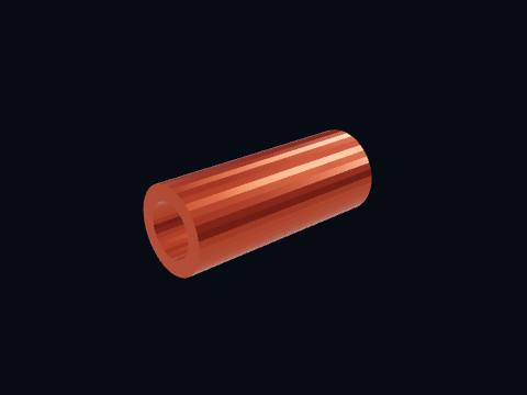
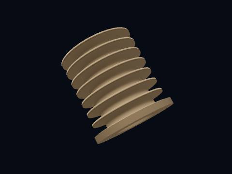
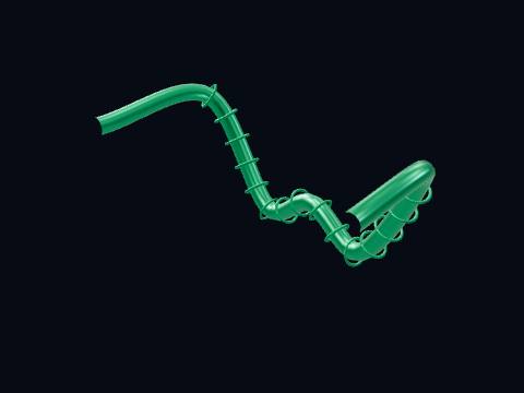
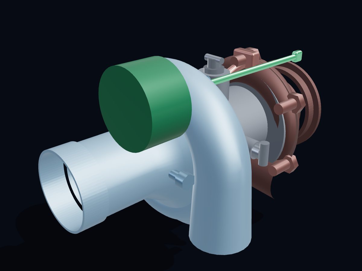
The intercooler: a finned copper tube from the LP head to the HP head, right in the flywheel fan's air blast. It cools the first-stage air before the second stage, so the HP cylinder has less work to do and the air stays cooler.
More about this part
Without intercooling, two stages would save little: the gain of two-stage compression comes from removing heat between the stages.
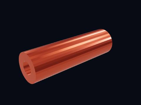
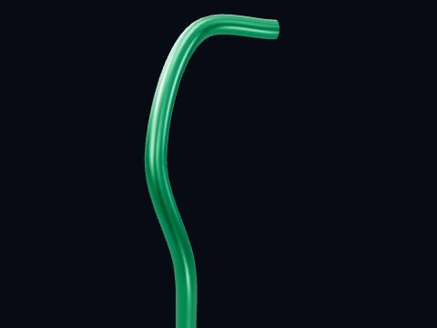
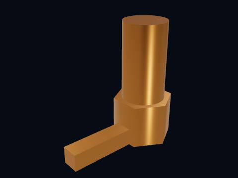
The discharge tube (aftercooler line) from the HP head down to the tank. The hot compressed air cools a little on the way, so some of its water vapour condenses in the tank instead of in the air lines.
The check (non-return) valve where the discharge tube enters the tank. It lets air into the tank but never back out, so the tank stays full when the pump stops.
Motor, motor pulley, V-belt, flywheel fan pulley and belt guard.
Flywheel fan pulley (Ø320 mm)
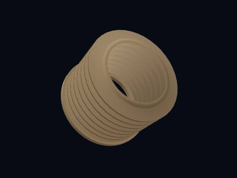
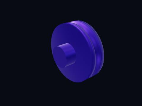
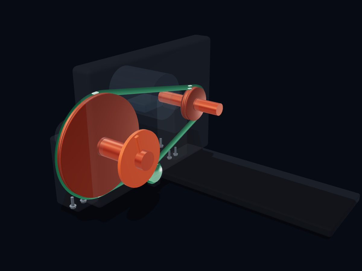
The flywheel pulley, Ø320 mm pitch diameter. Its heavy rim smooths out the uneven torque of the two strokes, and its spokes are shaped as fan blades that blow cooling air over the cylinders and the intercooler.
The V-belt carries power from the motor pulley to the compressor flywheel. A loose belt slips and squeals at start-up; an over-tight one wears the bearings.
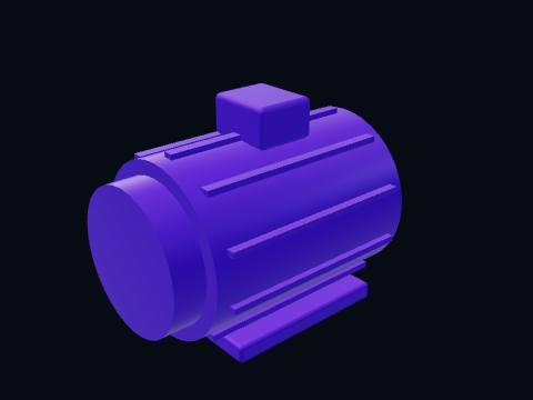
The driver: a 3.7 kW (5 hp) two-pole induction motor turning at about 2880 rpm on a 50 Hz supply. The pressure switch starts and stops it to keep the tank between its two set pressures.
The belt guard covers the flywheel and V-belt to protect the operator. A spinning flywheel and belt are an entanglement hazard, so every real compressor has one; it is drawn see-through here. Its mesh face still lets the fan pull air through.
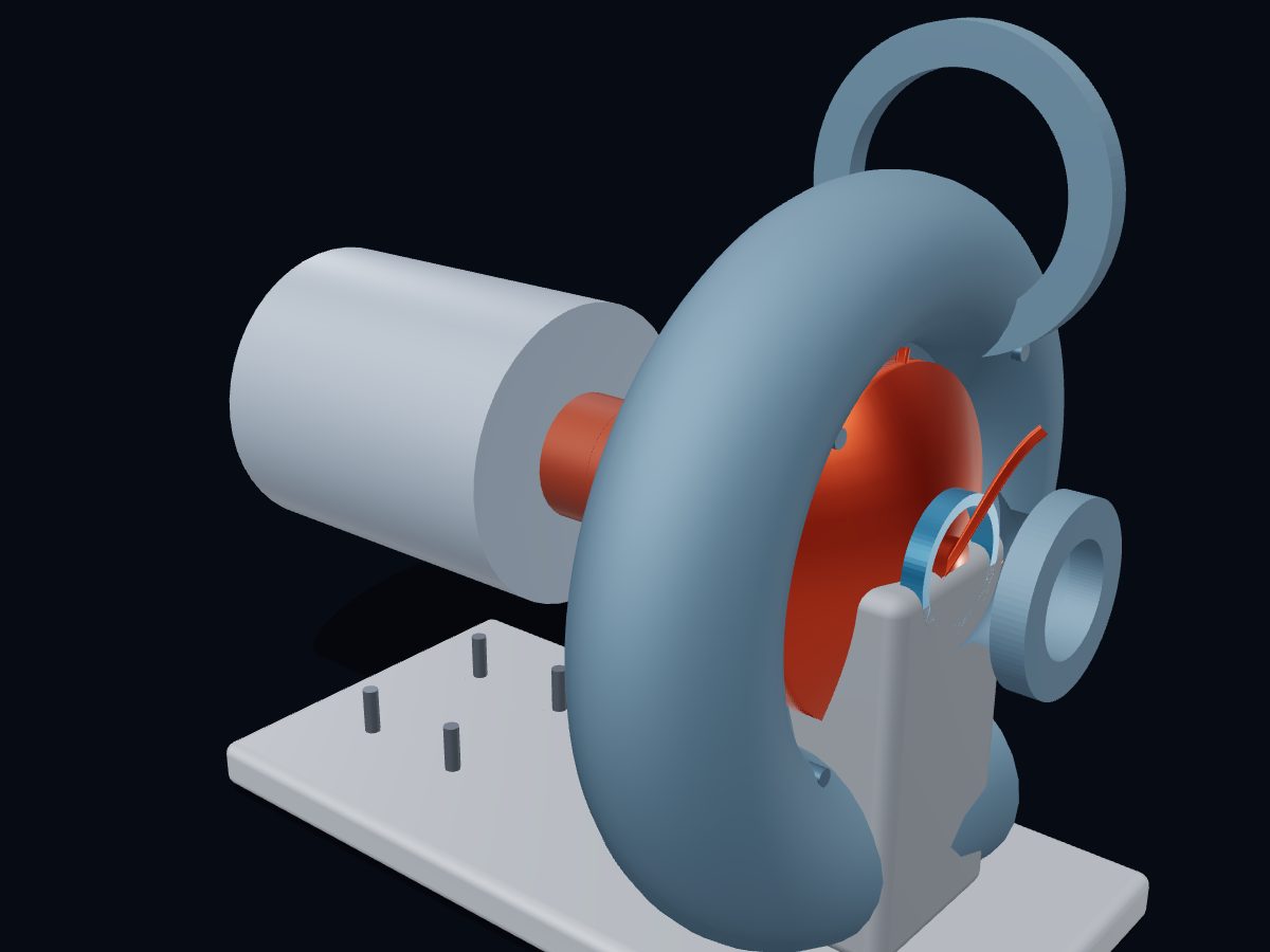
The air receiver (tank) stores compressed air so the compressor can stop and start instead of running all the time, evens out pressure pulses, and lets water and oil settle out.
More about this part
Pressure vessels like this are built and stamped to a code (e.g. ASME), and must be drained regularly.
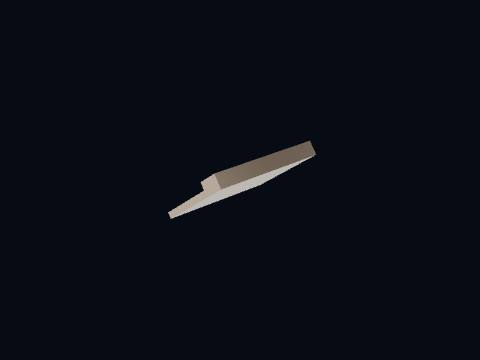
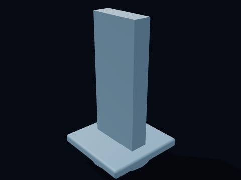
A tank foot supports the air receiver on the floor. Anti-vibration pads go under the feet; a compressor bolted rigidly to the floor shakes the tank welds.
Pressure switch with unloader, gauge, safety valve, service valve and drain.
Pressure switch with unloader
The pressure switch starts and stops the motor automatically. It stops the motor when the tank reaches its cut-out pressure and starts it again when pressure falls to the cut-in setting. Its built-in unloader vents the discharge line each time the motor stops, so the motor can restart without pushing against full pressure.
The tank pressure gauge shows how much air pressure is stored in the receiver. Watching how fast it climbs after a start is the simplest test of a worn compressor.
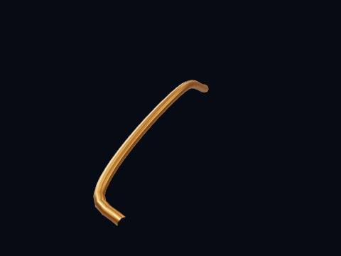
The unloader tube, from the check valve to the pressure switch. When the motor stops, the air trapped between the pump and the check valve escapes through it with a short hiss.
The safety (pressure relief) valve protects the tank from over-pressure. If the pressure switch ever fails to stop the motor, this spring-loaded valve pops open before the tank can be over-pressurised.
More about this part
Never plug or tie down a safety valve; pull its ring now and then to check it is not stuck.
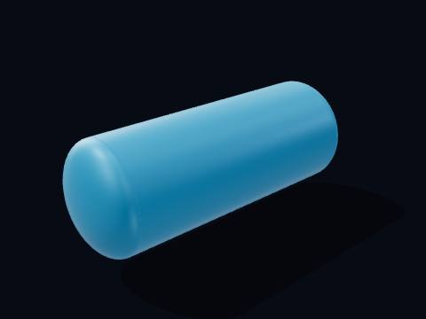
The drain valve at the lowest point of the tank. Compressing air also concentrates its water vapour; the water collects here and must be drained, or it rusts the tank from inside.
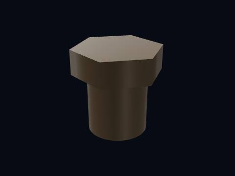
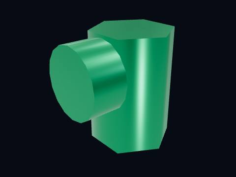
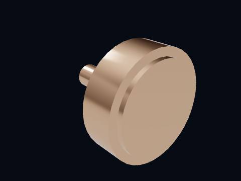
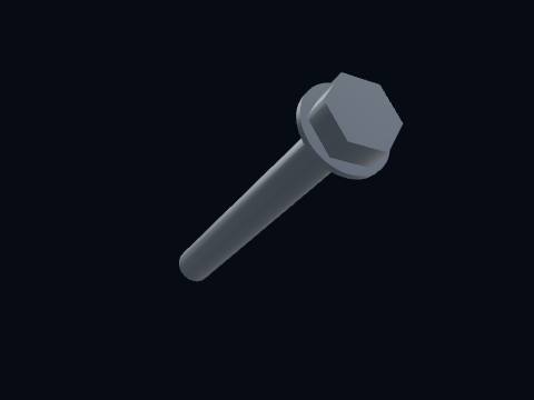
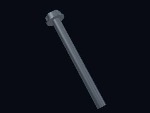
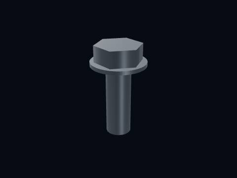
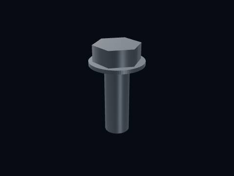
A cylinder head bolt clamps the head to the cylinder. Four per head clamp the head, valve plate and gaskets to the barrel against full delivery pressure.
A cylinder head bolt clamps the head to the cylinder. Four per head clamp the head, valve plate and gaskets to the barrel against full delivery pressure.
Is the reciprocating air compressor 3D model free to download?
Yes. The reciprocating air compressor 3D model is free for personal and educational use under CC BY-NC 4.0: credit "Engine-X by Parth Parmar (engx3d.com)". Selling the files or prints, or other commercial use, needs written permission.
Which file formats is the reciprocating air compressor 3D model in?
GLB (glTF 2.0) with colours and named parts, STL in millimetres (Z-up) for CAD, slicers and 3D printing, USDZ for AR on iPhone, and a ZIP with all 43 parts as separate STL files.
How many parts does the reciprocating air compressor 3D model have?
61 named pieces in 7 systems (crank train, cylinders & valves, air path, motor & belt drive, air receiver, controls & safety, hardware). Repeated pieces such as bolts are folded together, which leaves 43 different parts, each one downloadable on its own.
Can I 3D print the reciprocating air compressor model?
Yes, download the STL (whole machine or single parts) and open it in your slicer. It is a learning model at real scale, not a print kit: some parts touch or overlap and there are no fit tolerances, so scale it and print parts one by one.
How do I see the reciprocating air compressor in AR on my phone?
Tap "View in your room" on this page. Android opens Google Scene Viewer and iPhone opens AR Quick Look, both without an app, and you can place the model at real size on the floor or a table.
Can I see the reciprocating air compressor working in 3D?
Yes. Tap "Play live 3D here" or open the Engine-X atlas (engx3d.com/atlas#m=aircomp): it runs in the browser with true motion, and you can explode it, cut it open and X-ray it.
How to credit or cite this model
Credit line: Reciprocating air compressor 3D model, Engine-X by Parth Parmar (engx3d.com)
Citation: Parmar, P. (2026). Reciprocating air compressor 3D model [3D model, CC BY-NC 4.0]. Engine-X. https://engx3d.com/3d-models/reciprocating-air-compressor
Used this model?
For a class, a project, a print or a video? Tell us how it went. With your OK, we may feature your work here.
 Open full screen →
 View in your room · AR