 View in your room · AR
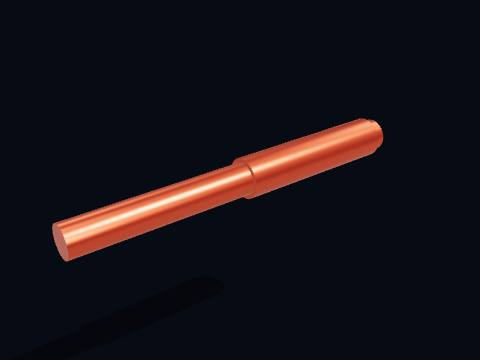
Input shaft
The input (high-speed) shaft, coupled to the motor. It turns at full motor speed, about 1440 rpm, and carries the small stage-1 pinion.
More about this part
- Speed: 1440 rpm
- Material: Alloy steel, hardened
Free 3D model · STL · GLB · AR
By Parth Parmar, mechanical design engineer · 51 pieces, 29 parts · Updated
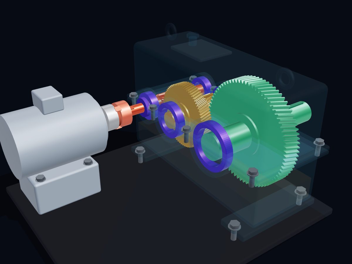
A gear reducer (gearbox) slows a motor down and multiplies its torque. A small gear on the fast input shaft drives a bigger gear on a slower shaft; the speed drops by the ratio of their tooth counts and the torque rises by almost the same factor. Two or more stages in series give big reductions.
 Open full screen →
Live 3D: drag to turn it, pinch to zoom, explode it, cut it open, X‑ray it and watch it run. Free, in your browser, no app. Open it full screen →
Single parts: scroll to the parts list. These are learning models, not a print kit: some parts touch or overlap and there are no fit tolerances.
Free for personal and educational use under CC BY-NC 4.0. Credit “Engine-X by Parth Parmar (engx3d.com)” when you share or remix it. Don’t sell the files or prints. For commercial use, get in touch. Every file carries the Engine-X mark and a hidden digital fingerprint that identifies it.
| Machine | Two-stage helical gearbox · 16 : 1 · 1440 → 90 rpm |
|---|---|
| Parts modeled | 51 named parts in 7 systems (29 different parts to download) |
| Model size | 628 × 353 × 503 mm (real scale) |
| Formats | GLB (glTF 2.0) 5.5 MB, STL 3.9 MB, USDZ for iPhone AR, ZIP of part STLs 0.9 MB |
| Live 3D | Engine‑X atlas: true motion, explode, section, X‑ray |
| License | CC BY-NC 4.0, free with credit |
| Input stage | 5 parts: Input shaft, stage-1 pinion, coupling hub and key: everything turning at motor speed. |
|---|---|
| Intermediate shaft | 3 parts: The shaft between the stages, with the big stage-1 gear and the small stage-2 pinion. |
| Output stage | 3 parts: Output gear, output shaft and key: slow speed, high torque. |
| Bearings & seals | 6 parts: Six tapered roller bearings, two oil seals and the bearing covers. |
| Housing & lubrication | 6 parts: Split cast-iron housing, cover, breather, sight glass, drain plug and the oil itself. |
| Motor & base | 3 parts: Motor, coupling hub and the common base frame. |
| Hardware | 3 parts: Cover, foot and motor bolts. |
Every part with a picture, what it does and its own STL file: input shaft, stage-1 pinion (18 teeth), input shaft key, coupling hub (gearbox side), coupling spider, intermediate shaft, stage-1 gear (72 teeth), stage-2 pinion (19 teeth) and more. Open any part in the live 3D atlas to see where it sits and how it moves. A part used several times (valves, bolts) is shown once with its count.
↓ Download all parts · ZIP · 0.9 MB
Input shaft, stage-1 pinion, coupling hub and key: everything turning at motor speed.
The input (high-speed) shaft, coupled to the motor. It turns at full motor speed, about 1440 rpm, and carries the small stage-1 pinion.
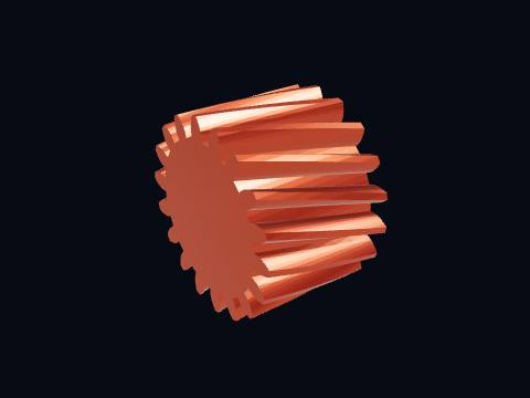
The stage-1 pinion, the smallest and fastest gear in the box. Its 18 helical teeth drive the 72-tooth gear, a 4 : 1 reduction. Helical teeth slide into mesh gradually from one end of the face to the other, so the drive is quieter and carries more load than straight spur teeth.
A pinion and its gear always have opposite helix hands: here the pinion is left hand and the gear right hand.

A parallel key. It locks a coupling or sprocket to the shaft so torque passes through the key, not through friction.
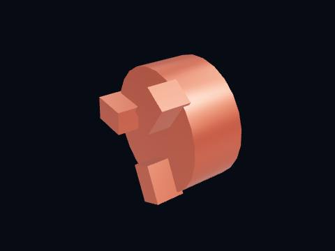
A flexible jaw coupling between motor and gearbox. Its elastomer spider soaks up small misalignment and torque shocks.
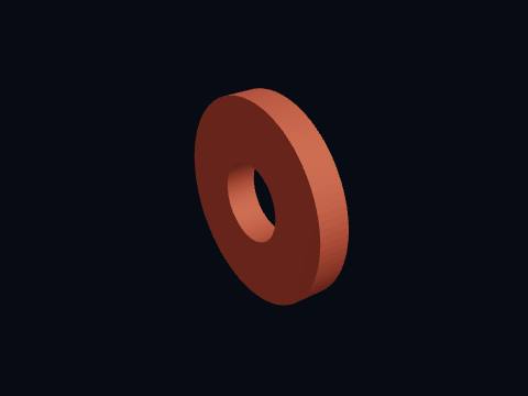
A flexible jaw coupling between motor and gearbox. Its elastomer spider soaks up small misalignment and torque shocks.
The shaft between the stages, with the big stage-1 gear and the small stage-2 pinion.
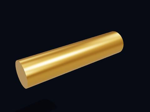
The intermediate shaft, between the two stages. It turns at 360 rpm and carries the big stage-1 gear and the small stage-2 pinion.
Both gears on this shaft have the same helix hand. One is driven and the other drives, so their axial thrusts push in opposite directions and partly cancel, which unloads the bearings.
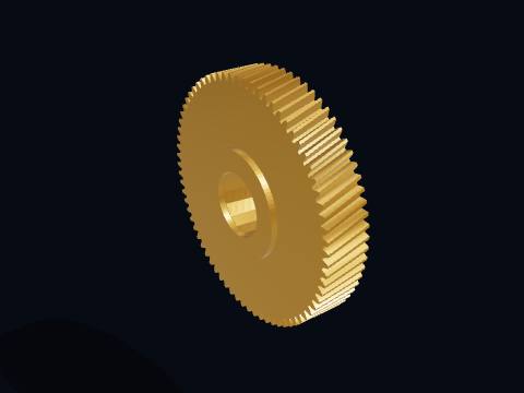
The stage-1 gear, 72 teeth. Four times the pinion's tooth count means it turns four times slower and carries four times the torque (minus a little friction).
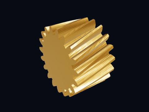
The stage-2 pinion, 19 teeth on a bigger module (3 mm), because the torque here is already four times higher than at the input.
Output gear, output shaft and key: slow speed, high torque.
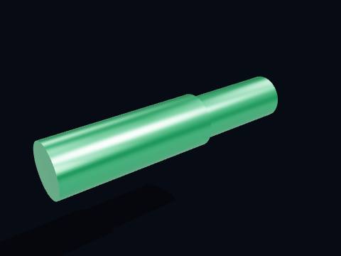
The output (low-speed) shaft. It turns 16 times slower than the motor, about 90 rpm, with roughly 153 N·m of torque from a 1.5 kW motor.
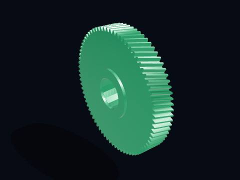
The output gear, 76 teeth, the largest part in the box. Its lowest teeth dip into the oil, so every turn it carries oil up into the meshes and flings it onto the walls for the bearings.

A parallel key. It locks a coupling or sprocket to the shaft so torque passes through the key, not through friction.
Six tapered roller bearings, two oil seals and the bearing covers.
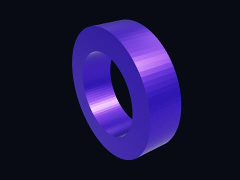
A tapered roller bearing, shown as its outer ring and cage. Helical teeth push the shafts sideways along their axes as well as sideways across them, so the bearings must take axial thrust as well as radial load; tapered rollers do both.

A tapered roller bearing, shown as its outer ring and cage. Helical teeth push the shafts sideways along their axes as well as sideways across them, so the bearings must take axial thrust as well as radial load; tapered rollers do both.

A tapered roller bearing, shown as its outer ring and cage. Helical teeth push the shafts sideways along their axes as well as sideways across them, so the bearings must take axial thrust as well as radial load; tapered rollers do both.

A radial lip oil seal where a shaft leaves the housing. A spring-loaded rubber lip rides on the turning shaft and keeps the oil in and the dirt out.

A radial lip oil seal where a shaft leaves the housing. A spring-loaded rubber lip rides on the turning shaft and keeps the oil in and the dirt out.

A bearing cover (end cap). It closes the bearing bore on the side where no shaft comes out and holds the bearing outer ring in place.
Split cast-iron housing, cover, breather, sight glass, drain plug and the oil itself.
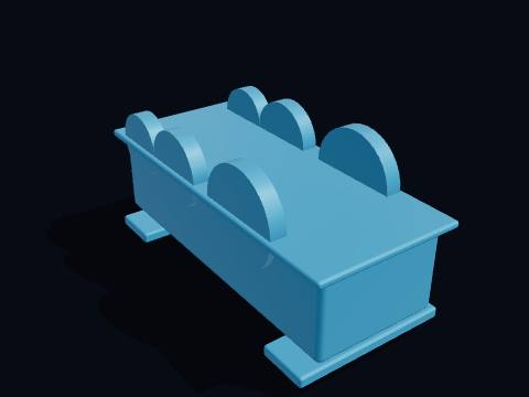
The lower housing, the gearbox body. It holds the bearing bores in exact alignment, carries the gear forces to the feet, and forms the oil sump.
The split line runs through the shaft centres, so the whole gear train can be lifted in or out from above.
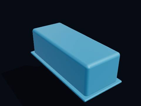
The upper housing (cover), bolted to the lower half along the split line. Drawn see-through so the gears stay visible.
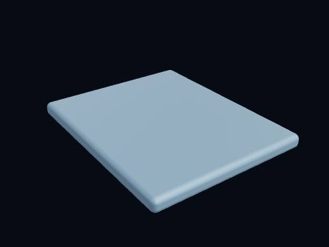
The inspection cover. Removing it lets a fitter look at the tooth contact pattern and the oil without opening the whole box.

The breather. As the gearbox warms up the air inside expands; the breather lets it out so pressure does not push oil past the seals. A blocked breather is a classic cause of leaking seals.

A lifting eye, cast into the cover for slinging the gearbox. It is rated for the gearbox alone, not with the motor attached.
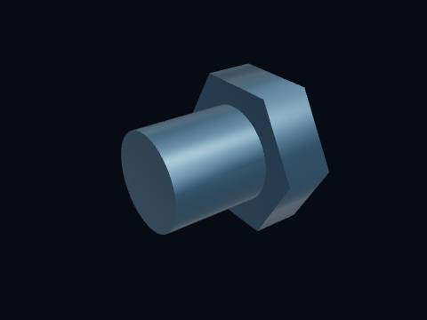
The magnetic drain plug at the lowest point of the sump. Its magnet catches steel wear particles, which makes it a cheap first check on gear and bearing wear.
Motor, coupling hub and the common base frame.

The common base frame. It keeps the motor and gearbox shafts lined up; misalignment here wears couplings, seals and bearings.
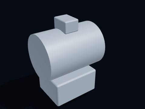
The driver: a 1.5 kW four-pole induction motor turning at about 1440 rpm on a 50 Hz supply. The gearbox turns its fast, low-torque output into slow, high-torque output.
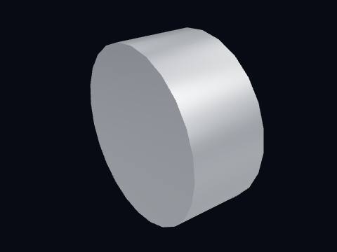
A flexible jaw coupling between motor and gearbox. Its elastomer spider soaks up small misalignment and torque shocks.
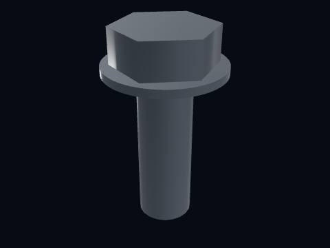
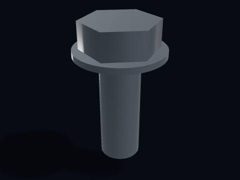
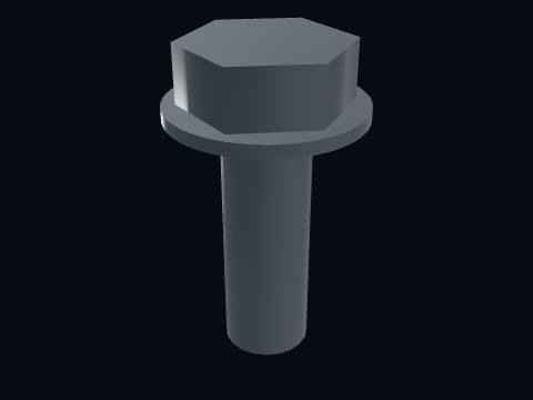
Cover, foot and motor bolts.
How does it work? Read the step-by-step guide, with key facts and common questions.
How a helical gear reducer works →Yes. The helical gear reducer 3D model is free for personal and educational use under CC BY-NC 4.0: credit "Engine-X by Parth Parmar (engx3d.com)". Selling the files or prints, or other commercial use, needs written permission.
GLB (glTF 2.0) with colours and named parts, STL in millimetres (Z-up) for CAD, slicers and 3D printing, USDZ for AR on iPhone, and a ZIP with all 29 parts as separate STL files.
51 named pieces in 7 systems (input stage, intermediate shaft, output stage, bearings & seals, housing & lubrication, motor & base, hardware). Repeated pieces such as bolts are folded together, which leaves 29 different parts, each one downloadable on its own.
Yes, download the STL (whole machine or single parts) and open it in your slicer. It is a learning model at real scale, not a print kit: some parts touch or overlap and there are no fit tolerances, so scale it and print parts one by one.
Tap "View in your room" on this page. Android opens Google Scene Viewer and iPhone opens AR Quick Look, both without an app, and you can place the model at real size on the floor or a table.
Yes. Tap "Play live 3D here" or open the Engine-X atlas (engx3d.com/atlas#m=gearbox): it runs in the browser with true motion, and you can explode it, cut it open and X-ray it.
Credit line: Helical gear reducer 3D model, Engine-X by Parth Parmar (engx3d.com)
Citation: Parmar, P. (2026). Helical gear reducer 3D model [3D model, CC BY-NC 4.0]. Engine-X. https://engx3d.com/3d-models/gear-reducer
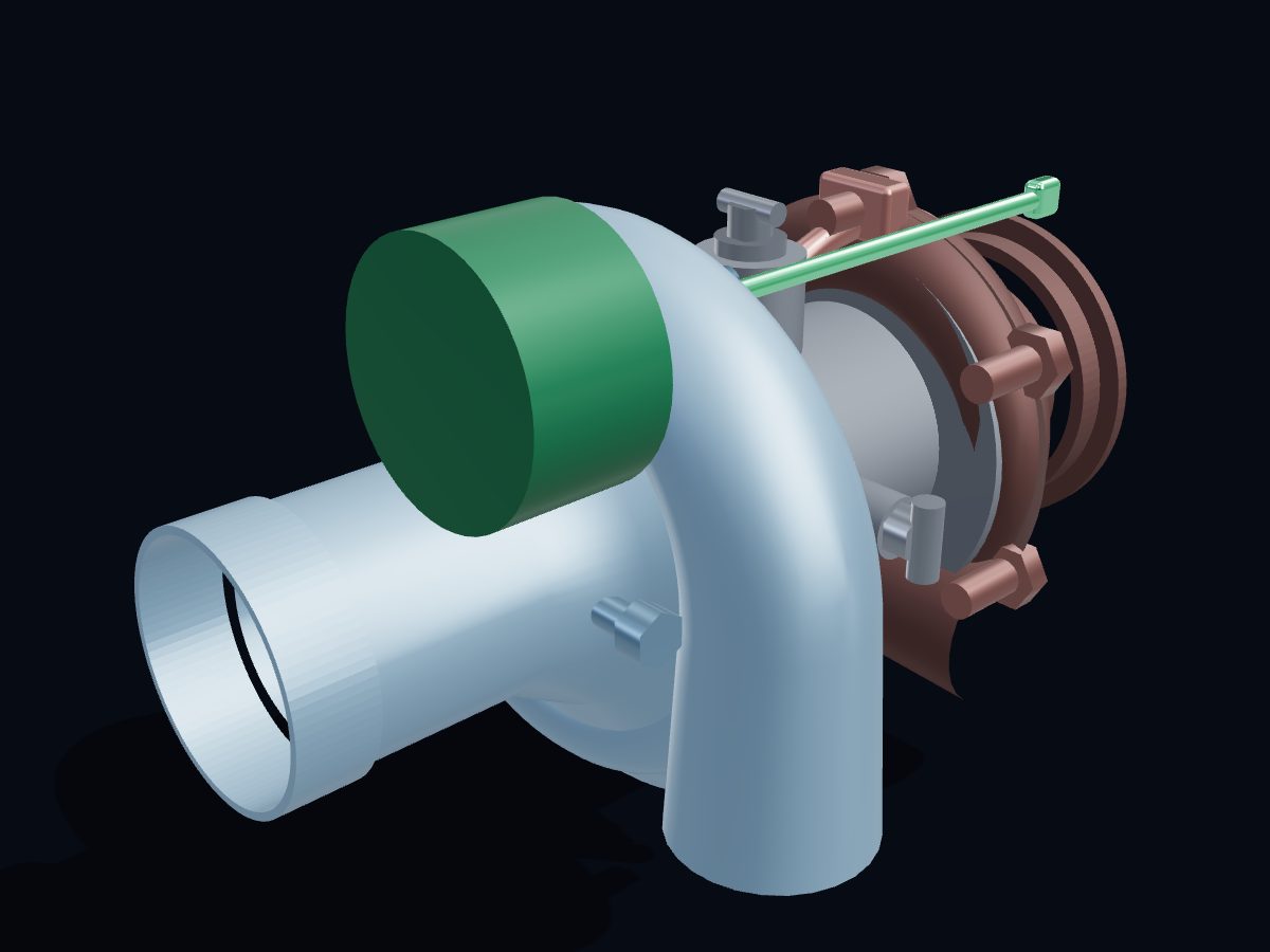 TurbochargerJournal-bearing turbo · Ø60 mm compressor · internal wastegateView and download →
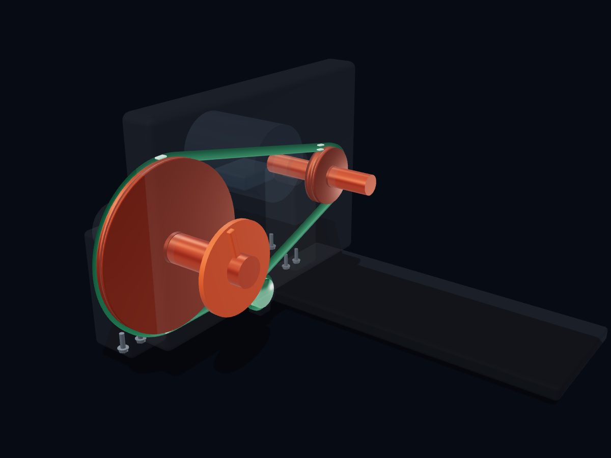 Pulley & belt driveV-belt speed reducer · Ø100/Ø250 mm pulleys · 2.50 : 1View and download →
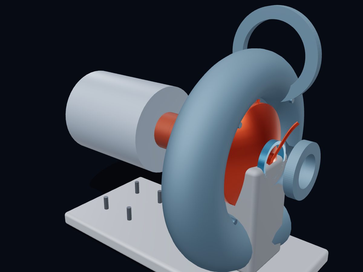 Centrifugal pumpSingle-stage end-suction · Ø164 mm impeller · 6 backward-curved vanesView and download →
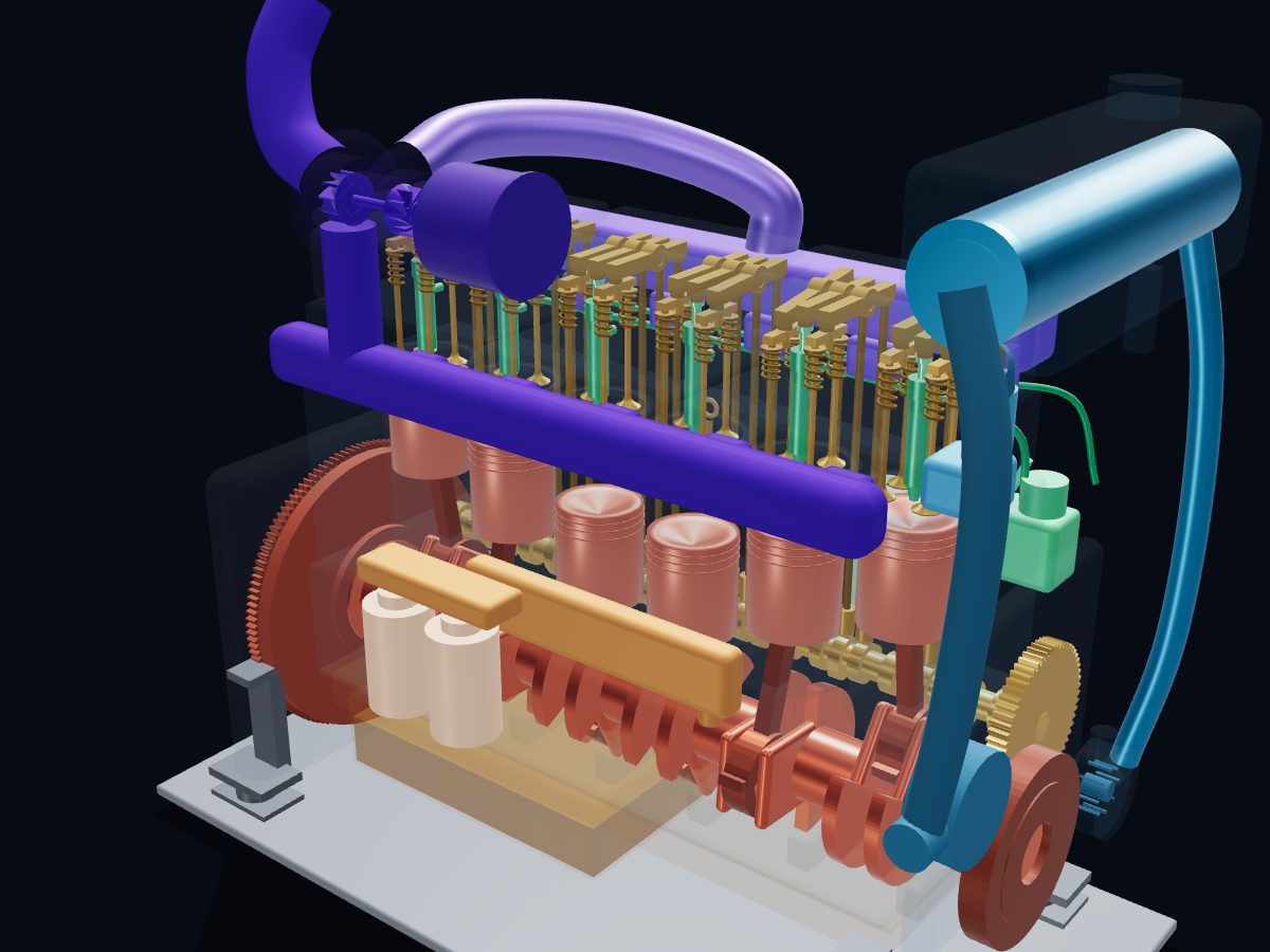 Marine diesel engineInline-6 · NT855 Big Cam style · 14 L · PT fuel systemView and download →
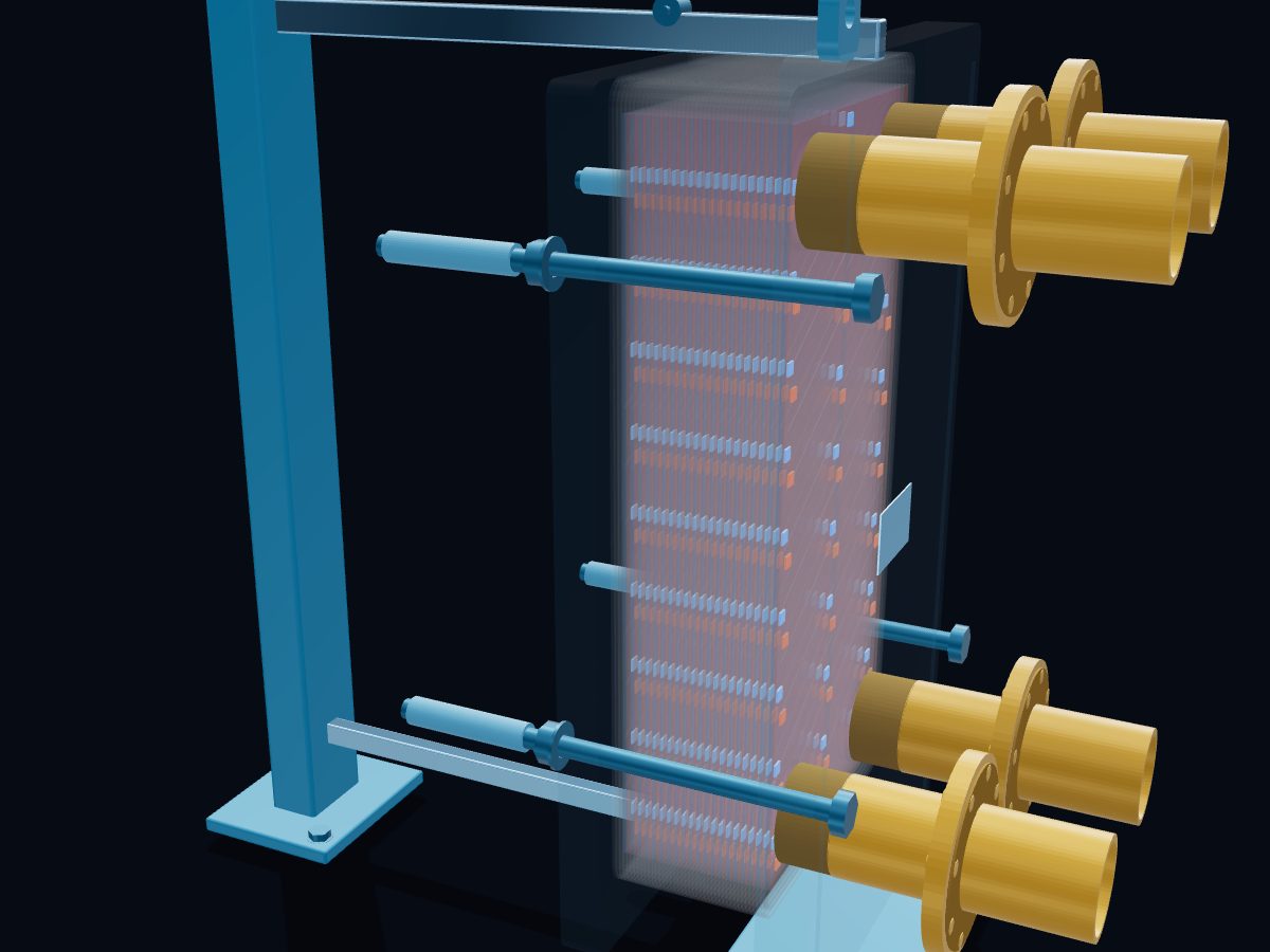 Plate heat exchangerGasketed, 41 plates · DN100 · countercurrentView and download →
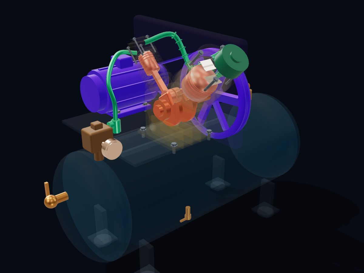 Reciprocating air compressorTwo-stage V-twin · 12 bar (175 psi) · 3.7 kWView and download →
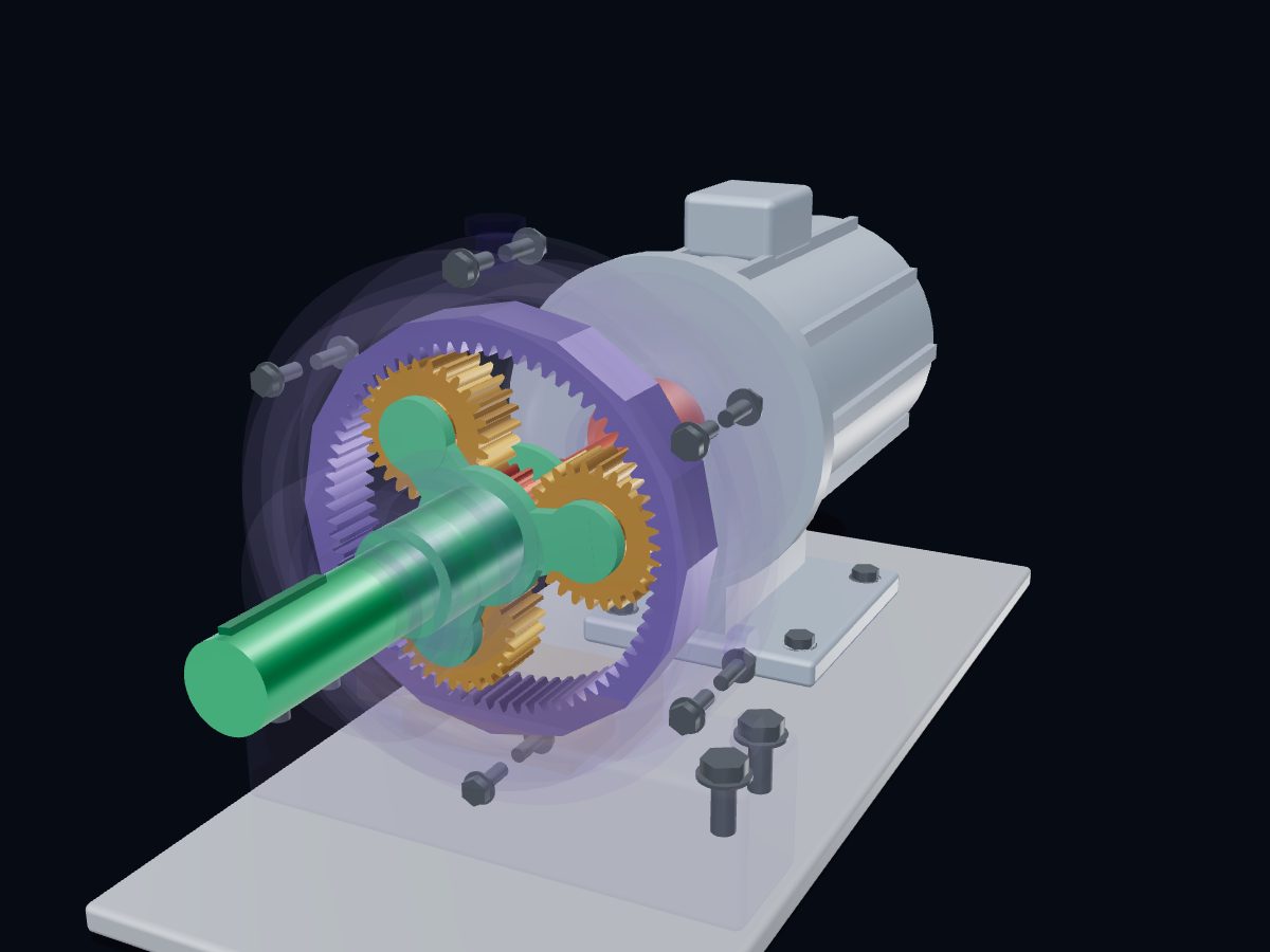 Planetary gearboxSun 18 · planets 3 × 27 · ring 72 · 5 : 1View and download →
All 3D models → · Live 3D atlas · Need an interactive 3D page for your own machine? Work with Engine‑X.