By Parth Parmar, mechanical design engineer · 64 pieces, 34 parts · Updated
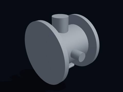
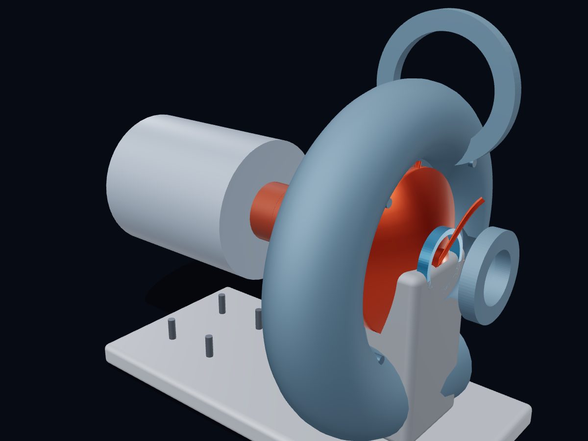
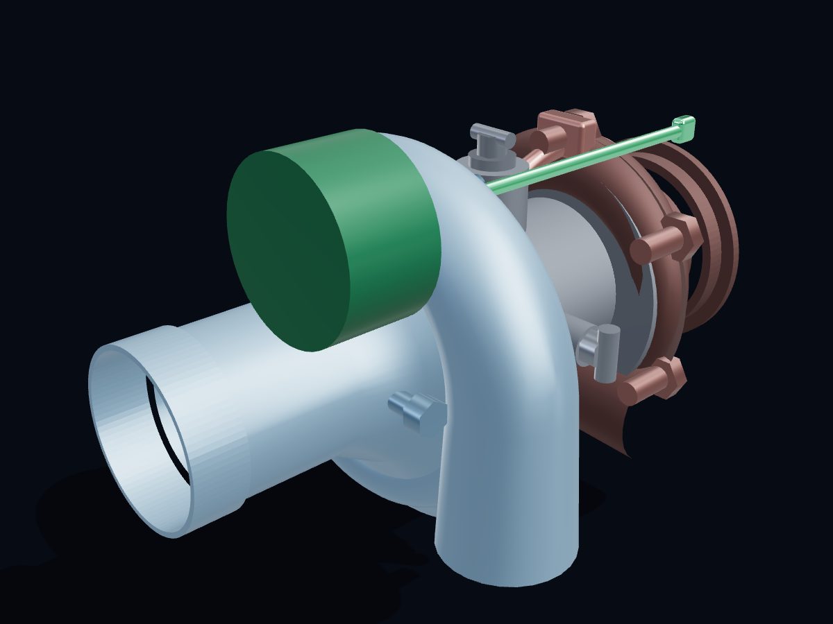
A turbocharger uses the engine's own exhaust gas to spin a turbine wheel. The turbine sits on the same shaft as a compressor wheel, which pulls in fresh air and pushes it into the engine under pressure. More air lets the engine burn more fuel, so a smaller engine can make the power of a bigger one.
Single parts: scroll to the parts list. These are learning models, not a print kit: some parts touch or overlap and there are no fit tolerances.
Free for personal and educational use under CC BY-NC 4.0. Credit “Engine-X by Parth Parmar (engx3d.com)” when you share or remix it. Don’t sell the files or prints. For commercial use, get in touch. Every file carries the Engine-X mark and a hidden digital fingerprint that identifies it.
Key facts
Machine
Journal-bearing turbo · Ø60 mm compressor · internal wastegate
Parts modeled
64 named parts in 5 systems (34 different parts to download)
Model size
261 × 188 × 205 mm (real scale)
Formats
GLB (glTF 2.0) 3.6 MB, STL 2.7 MB, USDZ for iPhone AR, ZIP of part STLs 0.6 MB
10 parts: Shaft, compressor wheel, turbine wheel, nut, collar and seal rings: everything that spins.
Bearing housing
9 parts: Centre housing, floating bearings, thrust bearing, oil and coolant connections.
Compressor stage
5 parts: Aluminum cover, inlet, backplate and diffuser: the cold side.
Turbine stage
6 parts: Cast-iron scroll, inlet flange, outlet, heat shield and clamps: the hot side.
Boost control
4 parts: Internal wastegate valve, arm, actuator and rod.
All 34 parts of the turbocharger, one by one
Every part with a picture, what it does and its own STL file: turbine shaft, compressor wheel (hub), compressor blade, splitter blade, compressor nut, turbine wheel (hub), turbine blade, thrust collar & oil slinger and more. Open any part in the live 3D atlas to see where it sits and how it moves. A part used several times (valves, bolts) is shown once with its count.
Shaft, compressor wheel, turbine wheel, nut, collar and seal rings: everything that spins.
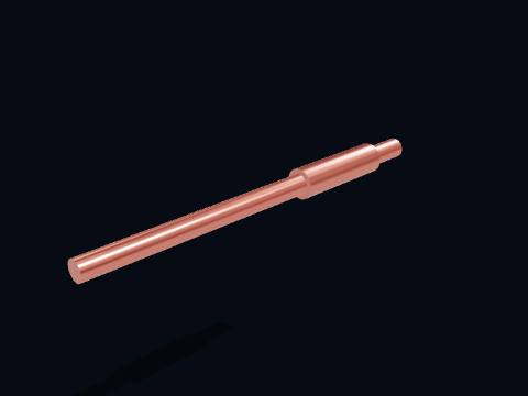
Turbine shaft
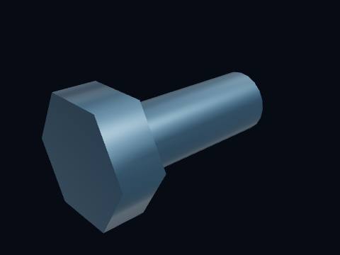
The turbine shaft joins the two wheels. The turbine wheel is friction-welded to one end; the compressor wheel is clamped on the other by a nut. At full boost it turns at 150,000 rpm or more, faster than anything else in the car.
More about this part
Balanced as an assembly to a fraction of a gram-millimetre; a speck of dirt is enough to shake it.
Runs on floating oil films only: no ball bearings in this design.
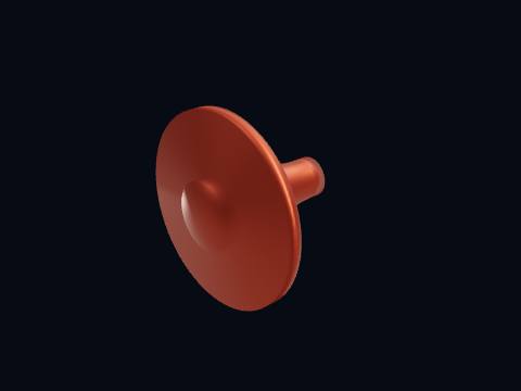
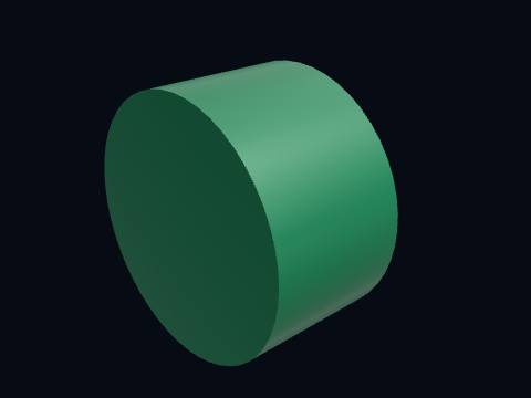
The compressor wheel draws air in axially at the inducer and flings it outward at the exducer. Its blades accelerate the air to over 300 m/s; the diffuser and scroll turn that speed into pressure.
More about this part
Machined from a forged aluminum billet or cast; some are titanium for high boost.
Tip speed at 150,000 rpm and 60 mm diameter is 470 m/s, above the speed of sound in the surrounding air.
Six main blades and six splitters: the splitters start further in so the inlet is not choked.
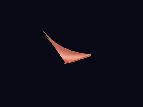
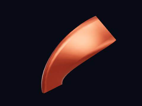
A full-length compressor blade, curving back against the direction of rotation at the exit (backsweep) so the flow leaves with less swirl and the pressure rise is more stable.
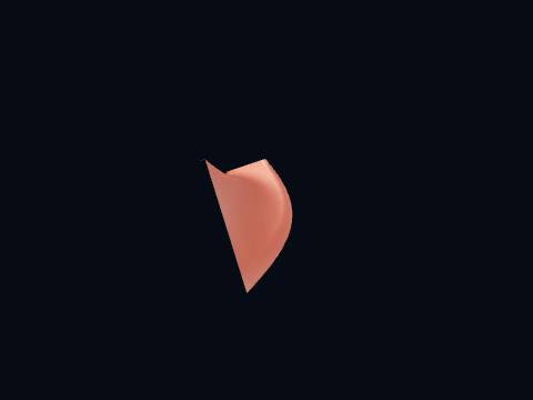
A splitter blade starts partway along the passage. It adds guiding surface where the passage is wide without crowding the inlet, where the full blades alone leave room for the air to enter.
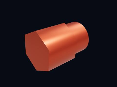
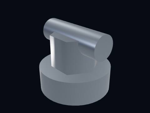
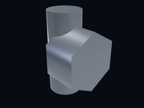
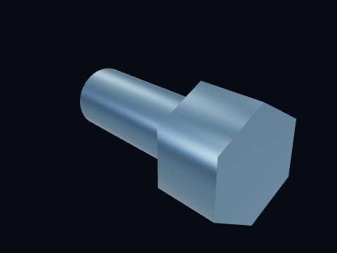
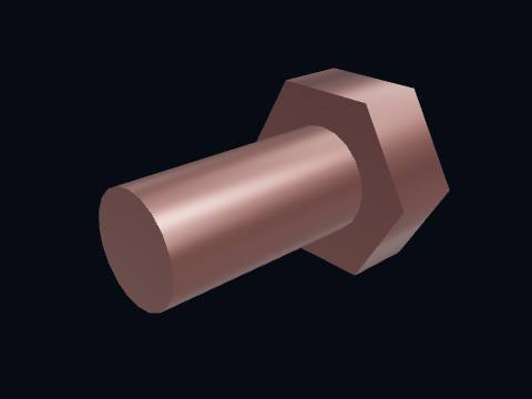
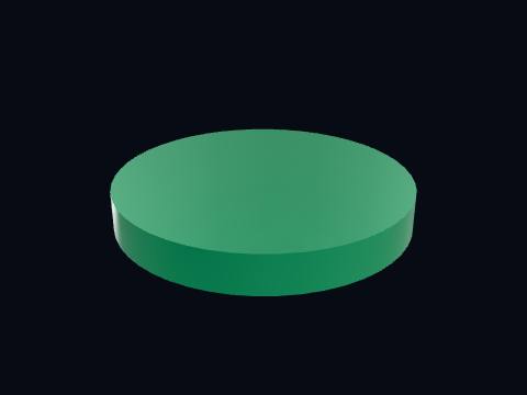
The compressor nut clamps the wheel to the shaft. It is torqued to a tiny value and its position is marked, because the whole rotor is balanced with it in place.
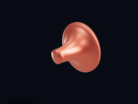
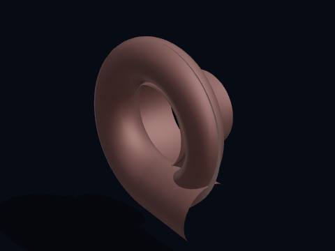
The turbine wheel is spun by exhaust gas at up to 950 °C. Gas enters radially from the scroll, expands through the blades and leaves axially, giving up its energy to drive the compressor.
More about this part
Investment-cast nickel superalloy, because nothing else keeps its strength at exhaust temperature.
Radial-inflow turbines are compact and cheap; large engines use axial turbines instead.
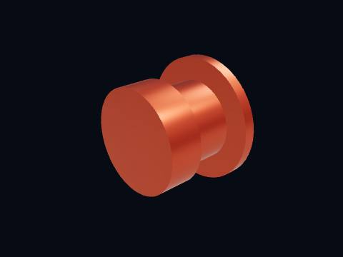
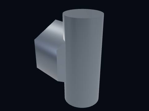
The thrust collar on the shaft runs against the thrust bearing pads and also carries the oil slinger that throws oil away from the compressor-side seal.
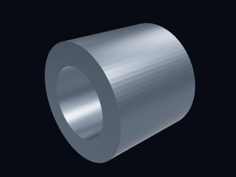
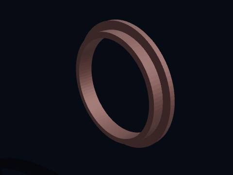
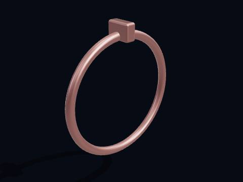
A piston-ring type seal that stops oil migrating along the shaft into the housings. Turbos rely on pressure difference more than on the ring itself, which is why a blocked drain smokes.
A piston-ring type seal that stops oil migrating along the shaft into the housings. Turbos rely on pressure difference more than on the ring itself, which is why a blocked drain smokes.
Centre housing, floating bearings, thrust bearing, oil and coolant connections.
Centre housing (CHRA)
The centre housing (CHRA: centre housing rotating assembly) carries the shaft in oil-fed journal bearings between the hot turbine and the cool compressor. Engine oil flows in from the top and drains from the bottom; a water jacket keeps it from coking after shutdown.
More about this part
Oil at 3–4 bar arrives through a banjo bolt; the drain must be gravity-fed and downhill.
Turbo timers exist because oil left standing here at 300 °C turns to carbon.
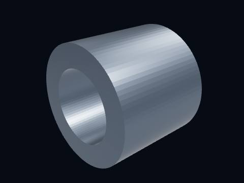
A floating journal bearing: a bronze bush that turns at about half shaft speed with oil films on both its inside and its outside. The double film damps shaft whirl that a fixed bush could not.
A floating journal bearing: a bronze bush that turns at about half shaft speed with oil films on both its inside and its outside. The double film damps shaft whirl that a fixed bush could not.
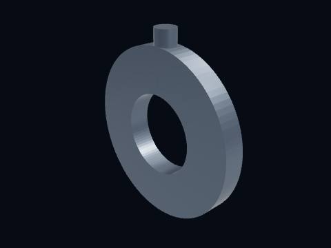
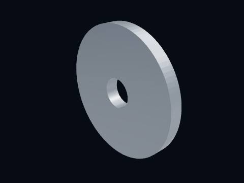
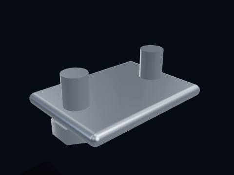
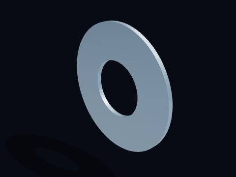
The thrust bearing takes the axial load from the pressure difference across the two wheels. It is a flat plate with tapered oil-wedge pads on both faces.
Aluminum cover, inlet, backplate and diffuser: the cold side.
Compressor housing
The compressor housing (cover) shrouds the wheel with a close-fitting contour, then collects the air in a scroll (volute) whose cross-section grows around the wheel so the flow speed stays constant as more air joins.
More about this part
Cast aluminum; the wheel-to-contour clearance is about 0.3 mm because every bit of leakage is lost efficiency.
Some housings have a ported shroud that recirculates a little air to widen the surge margin.
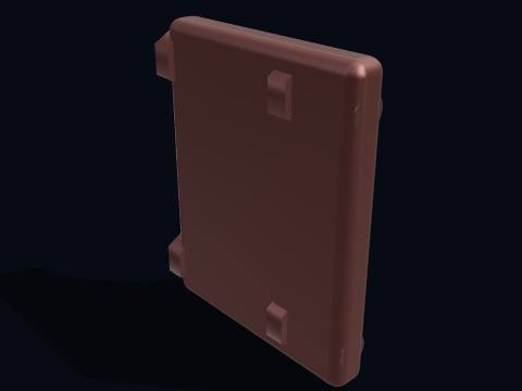
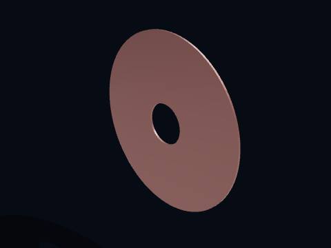
The compressor backplate closes the wheel’s back face and carries the vaneless diffuser: the parallel gap between backplate and cover where the air slows down and gains pressure before reaching the scroll.
A shaft speed sensor reading the passing compressor blades, so the engine controller can keep the rotor below its speed limit rather than guessing from pressure.
Cast-iron scroll, inlet flange, outlet, heat shield and clamps: the hot side.
Turbine housing
The turbine housing: a cast-iron scroll that takes exhaust from the manifold flange and wraps it around the turbine wheel. Its cross-section shrinks around the wheel (the reverse of the compressor) so the gas keeps its speed as it is fed inward.
More about this part
The A/R ratio (scroll area over its centroid radius) sets how fast the turbo spools versus how much it flows at the top end.
Runs cherry red under full load; ductile iron with high silicon and molybdenum survives the cycling.
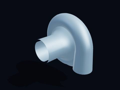
A stamped stainless shield between the turbine housing and the centre housing. It keeps radiant heat from the turbine scroll away from the bearing oil.
The internal wastegate is a flap valve in the turbine housing that lets exhaust bypass the wheel once boost reaches the target. Opening it caps turbine power and therefore boost pressure.
More about this part
Shown cycling open and closed. In service it cracks open only as far as needed to hold the set boost.
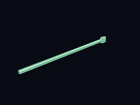
The wastegate actuator: a spring-loaded diaphragm can. Boost pressure from the compressor outlet pushes the diaphragm against the spring; above the set pressure the rod moves and opens the wastegate.
More about this part
The spring preload sets the base boost; the engine controller bleeds the signal with a solenoid to raise it.
Yes. The turbocharger 3D model is free for personal and educational use under CC BY-NC 4.0: credit "Engine-X by Parth Parmar (engx3d.com)". Selling the files or prints, or other commercial use, needs written permission.
Which file formats is the turbocharger 3D model in?
GLB (glTF 2.0) with colours and named parts, STL in millimetres (Z-up) for CAD, slicers and 3D printing, USDZ for AR on iPhone, and a ZIP with all 34 parts as separate STL files.
How many parts does the turbocharger 3D model have?
64 named pieces in 5 systems (rotating group, bearing housing, compressor stage, turbine stage, boost control). Repeated pieces such as bolts are folded together, which leaves 34 different parts, each one downloadable on its own.
Can I 3D print the turbocharger model?
Yes, download the STL (whole machine or single parts) and open it in your slicer. It is a learning model at real scale, not a print kit: some parts touch or overlap and there are no fit tolerances, so scale it and print parts one by one.
How do I see the turbocharger in AR on my phone?
Tap "View in your room" on this page. Android opens Google Scene Viewer and iPhone opens AR Quick Look, both without an app, and you can place the model at real size on the floor or a table.
Can I see the turbocharger working in 3D?
Yes. Tap "Play live 3D here" or open the Engine-X atlas (engx3d.com/atlas#m=turbo): it runs in the browser with true motion, and you can explode it, cut it open and X-ray it.
How to credit or cite this model
Credit line: Turbocharger 3D model, Engine-X by Parth Parmar (engx3d.com)
Citation: Parmar, P. (2026). Turbocharger 3D model [3D model, CC BY-NC 4.0]. Engine-X. https://engx3d.com/3d-models/turbocharger
Used this model?
For a class, a project, a print or a video? Tell us how it went. With your OK, we may feature your work here.
 Open full screen →
 View in your room · AR