 View in your room · AR
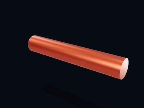
Driver shaft
The driver shaft, coupled directly to the motor. It turns at motor speed — there is no reduction before the belt.
More about this part
- Material: Steel
- Diameter: Ø 36 mm
Free 3D model · STL · GLB · AR
By Parth Parmar, mechanical design engineer · 26 pieces, 20 parts · Updated
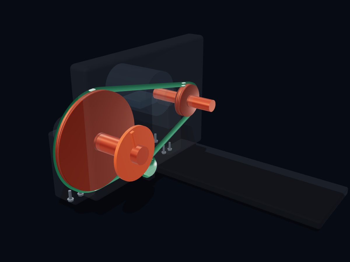
A V-belt drive passes rotation from one shaft to another through a belt wedged in grooved pulleys. The belt moves at the same speed around both pulleys, so the smaller pulley turns faster and the larger one turns slower. The speed ratio equals the ratio of the pulley diameters.
 Open full screen →
Live 3D: drag to turn it, pinch to zoom, explode it, cut it open, X‑ray it and watch it run. Free, in your browser, no app. Open it full screen →
Single parts: scroll to the parts list. These are learning models, not a print kit: some parts touch or overlap and there are no fit tolerances.
Free for personal and educational use under CC BY-NC 4.0. Credit “Engine-X by Parth Parmar (engx3d.com)” when you share or remix it. Don’t sell the files or prints. For commercial use, get in touch. Every file carries the Engine-X mark and a hidden digital fingerprint that identifies it.
| Machine | V-belt speed reducer · Ø100/Ø250 mm pulleys · 2.50 : 1 |
|---|---|
| Parts modeled | 26 named parts in 4 systems (20 different parts to download) |
| Model size | 755 × 409 × 621 mm (real scale) |
| Formats | GLB (glTF 2.0) 1.7 MB, STL 1.3 MB, USDZ for iPhone AR, ZIP of part STLs 0.2 MB |
| Live 3D | Engine‑X atlas: true motion, explode, section, X‑ray |
| License | CC BY-NC 4.0, free with credit |
| Drive train | 5 parts: Driver shaft, driven shaft, both pulleys and the speed-indicator disc. |
|---|---|
| Belt & idler | 3 parts: The V-belt, its reference marks, and the free-spinning idler pulley. |
| Frame & mounts | 6 parts: Base plate, motor, pillow blocks, idler bracket and belt guard. |
| Hardware | 6 parts: Mounting and pivot bolts. |
Every part with a picture, what it does and its own STL file: driver shaft, driver pulley (ø100 mm), driven shaft, driven pulley (ø250 mm), speed-indicator disc, idler pulley (ø50 mm), v-belt, belt reference mark and more. Open any part in the live 3D atlas to see where it sits and how it moves. A part used several times (valves, bolts) is shown once with its count.
↓ Download all parts · ZIP · 0.2 MB
Driver shaft, driven shaft, both pulleys and the speed-indicator disc.
The driver shaft, coupled directly to the motor. It turns at motor speed — there is no reduction before the belt.
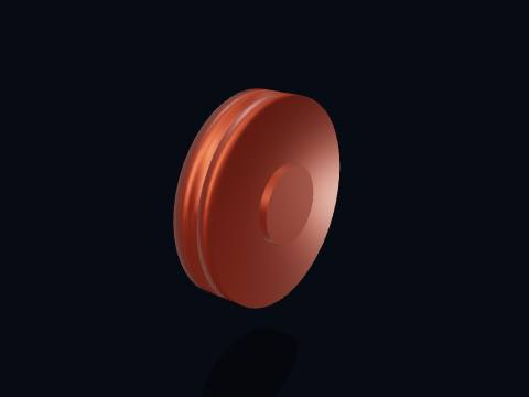
The driver pulley. Its radius is the whole reason a belt drive can change speed at all: the belt must travel the same distance per second at both pulleys, so a small pulley here has to spin faster than a big one downstream.
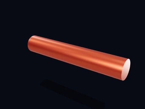
The driven (output) shaft. Whatever it feeds — a pump, a fan, a conveyor — sees whatever speed the pulley ratio has left it with.
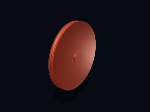
The driven pulley, 2.50× the driver's radius. Because belt speed is the same all the way round the loop, this pulley turns exactly 2.50× slower than the driver — a plain speed reducer with no gear teeth at all.
Unlike a meshing gear pair, both pulleys turn the same way round. Crossing the belt into a figure-eight is the only way to reverse it.
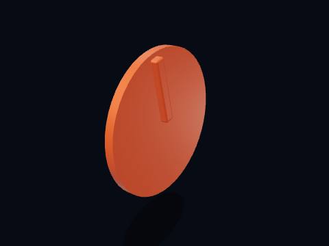
A speed-indicator disc on the output shaft. The stripe is a strobe/tachometer reference mark — a fixed light flashed at the shaft’s true speed would make it appear to stand still.
The V-belt, its reference marks, and the free-spinning idler pulley.
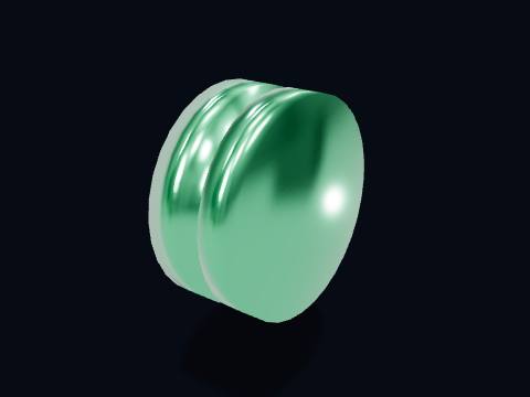
An idler pulley, carrying no load of its own. It presses on the belt’s slack side purely to keep enough tension in the loop for the wedging action to grip — too little tension and the belt slips; too much and it cooks the bearings.

The V-belt: a closed loop of rubber over steel or polyester cords, wedged into the pulleys’ grooves. Wedging (not just friction on a flat face) is what lets it grip hard enough to transmit real power without slipping.
Runs slightly under the pulleys’ outer diameter, on the cord line partway down the V, which is the "effective" radius the speed ratio really uses.
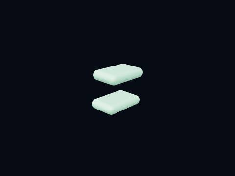
A painted reference mark. It isn’t a real part of the belt — it’s here so the belt’s motion is visible. Watch it travel: its speed along the loop never changes, even though the two pulleys spin at very different rates. That constant loop speed is the entire mechanism of a belt drive.
Base plate, motor, pillow blocks, idler bracket and belt guard.
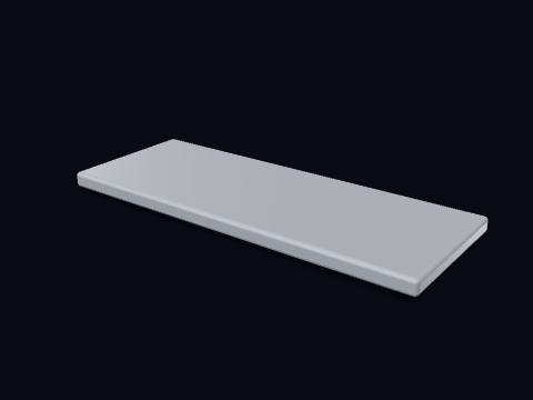
The base plate. It fixes the centre distance between the two shafts, which is what fixes the amount of wrap the belt gets around each pulley.
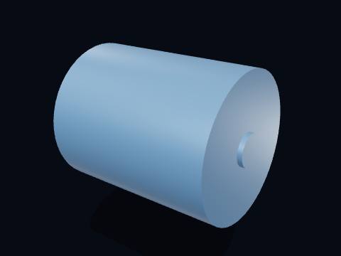
The driver: an electric motor. Its shaft turns at a constant speed set by the supply frequency (or by a variable-frequency drive), and that speed is all this whole machine has to work with — everything downstream is a ratio of it.
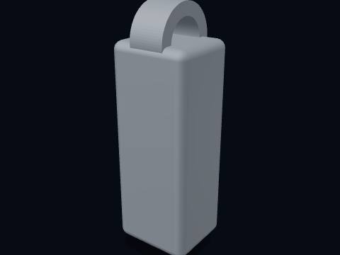
A pillow block (plummer block): a bearing housing bolted to the base that lets a shaft spin freely while carrying its weight and the belt’s pull.
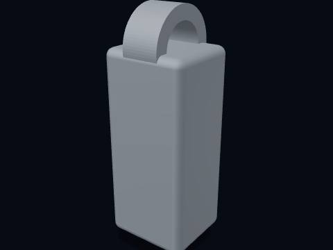
A pillow block (plummer block): a bearing housing bolted to the base that lets a shaft spin freely while carrying its weight and the belt’s pull.
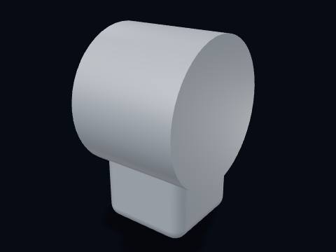
The idler bracket. Its mounting slot lets the idler be pushed in to tension a new belt, or to take up the slack as an old one stretches.
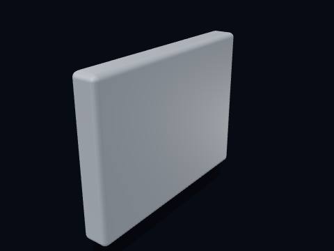
The belt guard. A spinning belt and two pulley nips are a serious entanglement hazard, so a guard covers them on every real machine; this one is drawn semi-transparent so the drive underneath stays visible.
Mounting and pivot bolts.
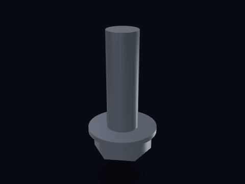
A hex bolt, holding one of the drive’s components to the base plate or to the pillow blocks.
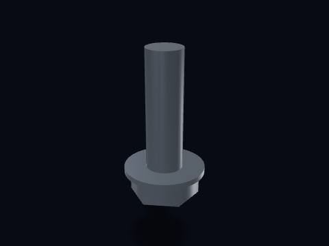
A hex bolt, holding one of the drive’s components to the base plate or to the pillow blocks.
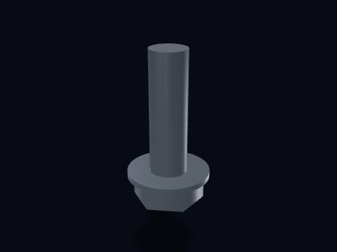
A hex bolt, holding one of the drive’s components to the base plate or to the pillow blocks.
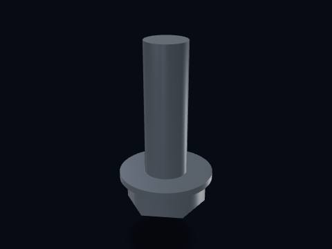
A hex bolt, holding one of the drive’s components to the base plate or to the pillow blocks.
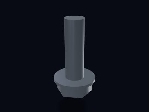
A hex bolt, holding one of the drive’s components to the base plate or to the pillow blocks.
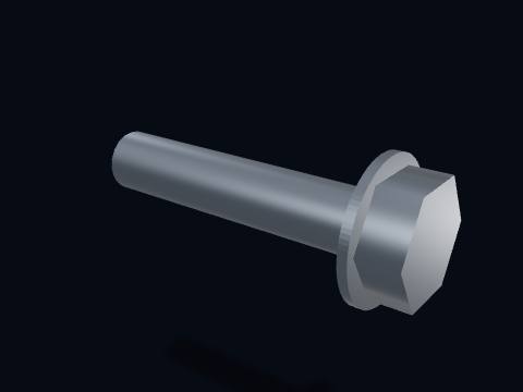
A hex bolt, holding one of the drive’s components to the base plate or to the pillow blocks.
How does it work? Read the step-by-step guide, with key facts and common questions.
How a pulley & belt drive works →Yes. The pulley & belt drive 3D model is free for personal and educational use under CC BY-NC 4.0: credit "Engine-X by Parth Parmar (engx3d.com)". Selling the files or prints, or other commercial use, needs written permission.
GLB (glTF 2.0) with colours and named parts, STL in millimetres (Z-up) for CAD, slicers and 3D printing, USDZ for AR on iPhone, and a ZIP with all 20 parts as separate STL files.
26 named pieces in 4 systems (drive train, belt & idler, frame & mounts, hardware). Repeated pieces such as bolts are folded together, which leaves 20 different parts, each one downloadable on its own.
Yes, download the STL (whole machine or single parts) and open it in your slicer. It is a learning model at real scale, not a print kit: some parts touch or overlap and there are no fit tolerances, so scale it and print parts one by one.
Tap "View in your room" on this page. Android opens Google Scene Viewer and iPhone opens AR Quick Look, both without an app, and you can place the model at real size on the floor or a table.
Yes. Tap "Play live 3D here" or open the Engine-X atlas (engx3d.com/atlas#m=pulleybelt): it runs in the browser with true motion, and you can explode it, cut it open and X-ray it.
Credit line: Pulley & belt drive 3D model, Engine-X by Parth Parmar (engx3d.com)
Citation: Parmar, P. (2026). Pulley & belt drive 3D model [3D model, CC BY-NC 4.0]. Engine-X. https://engx3d.com/3d-models/v-belt-drive
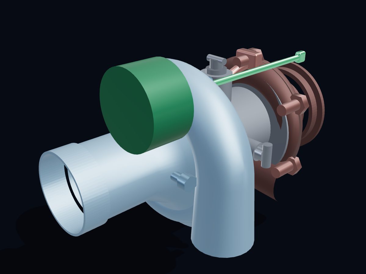 TurbochargerJournal-bearing turbo · Ø60 mm compressor · internal wastegateView and download →
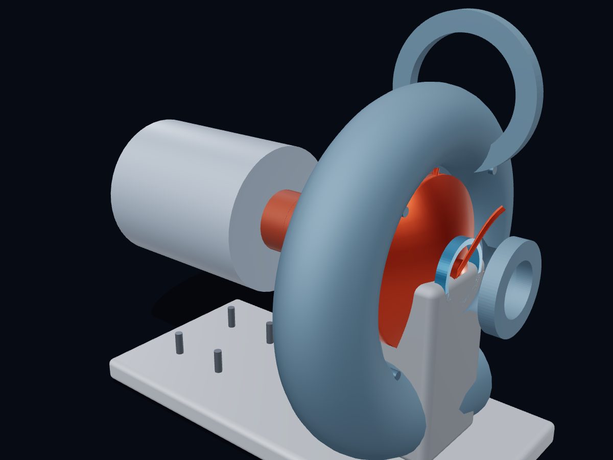 Centrifugal pumpSingle-stage end-suction · Ø164 mm impeller · 6 backward-curved vanesView and download →
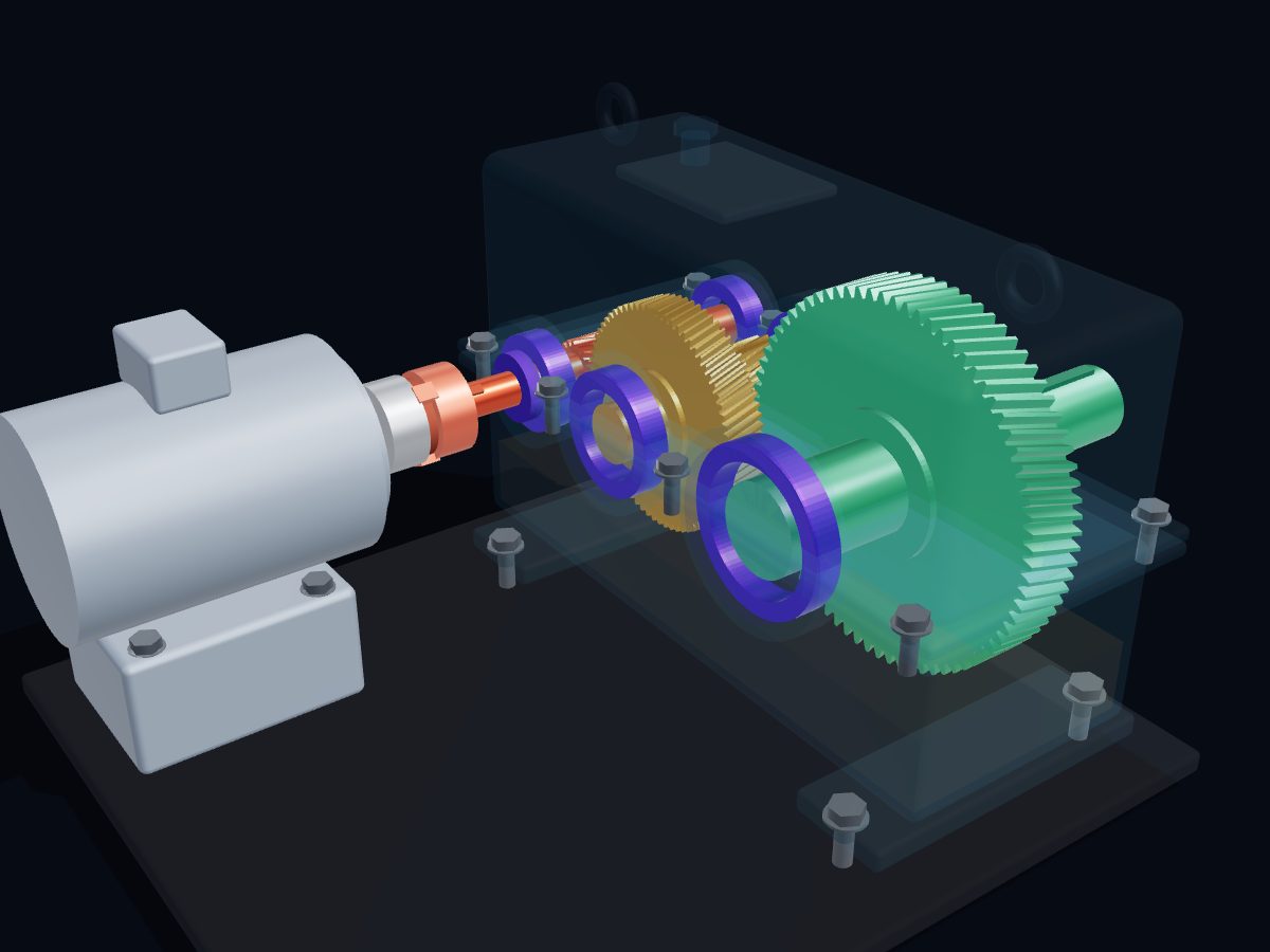 Helical gear reducerTwo-stage helical gearbox · 16 : 1 · 1440 → 90 rpmView and download →
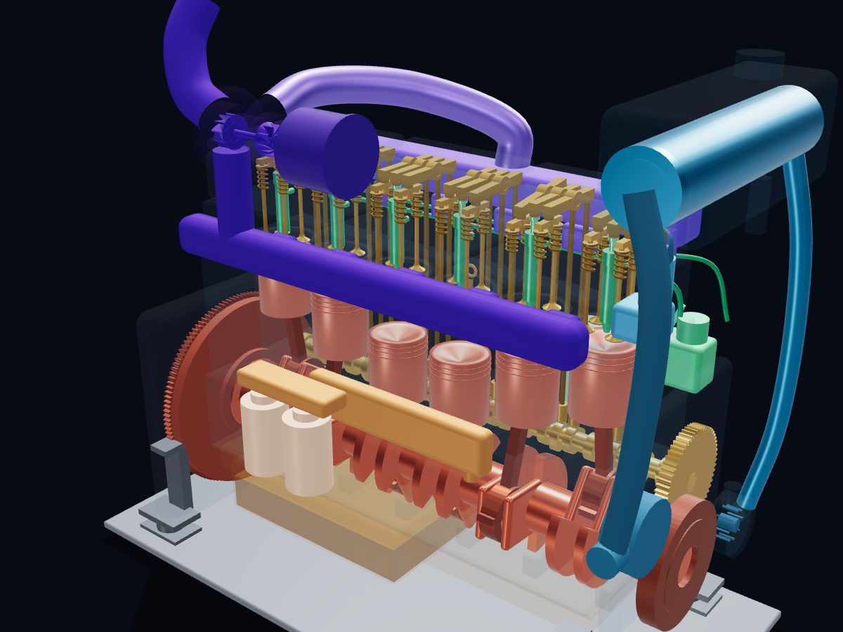 Marine diesel engineInline-6 · NT855 Big Cam style · 14 L · PT fuel systemView and download →
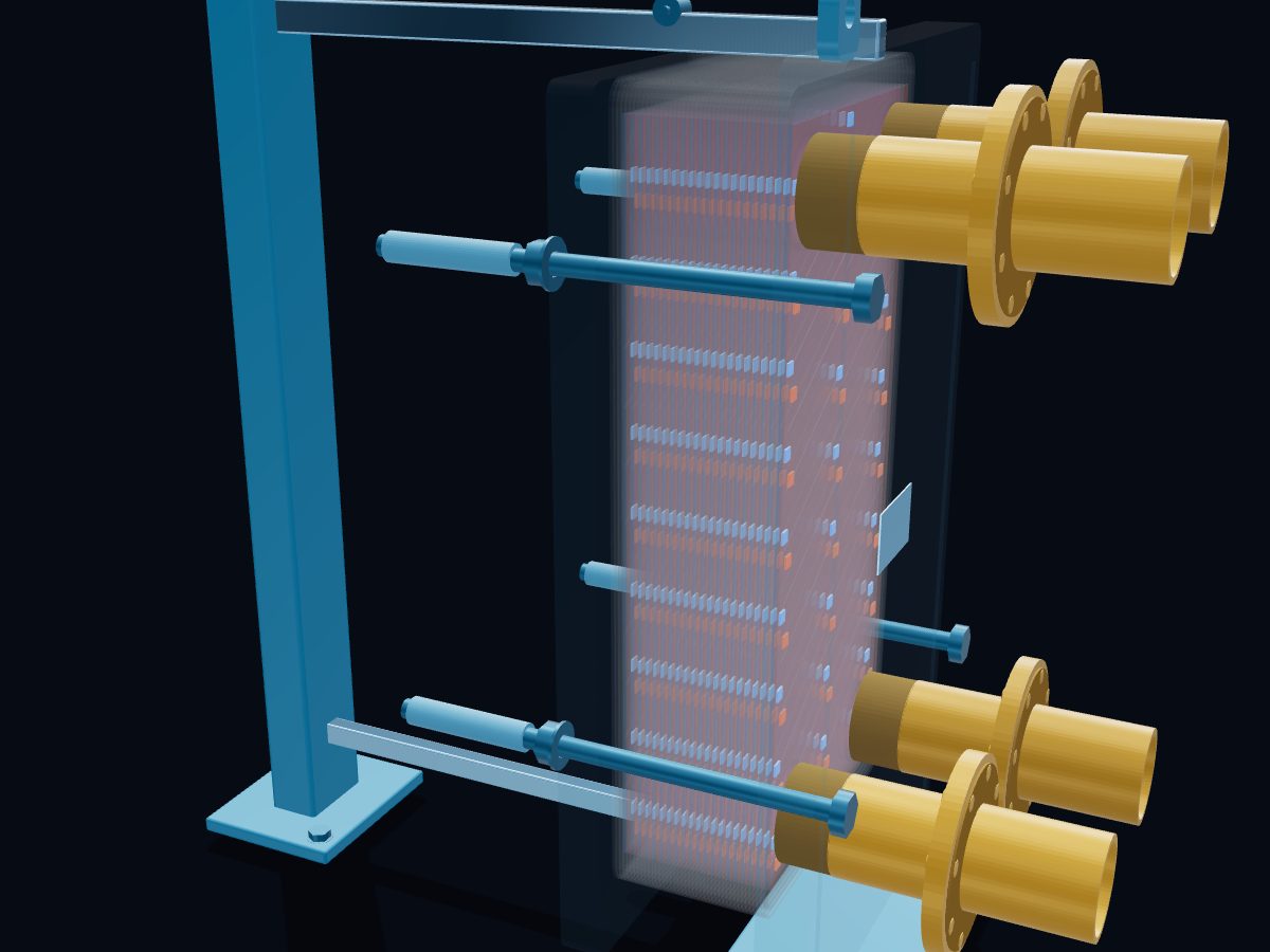 Plate heat exchangerGasketed, 41 plates · DN100 · countercurrentView and download →
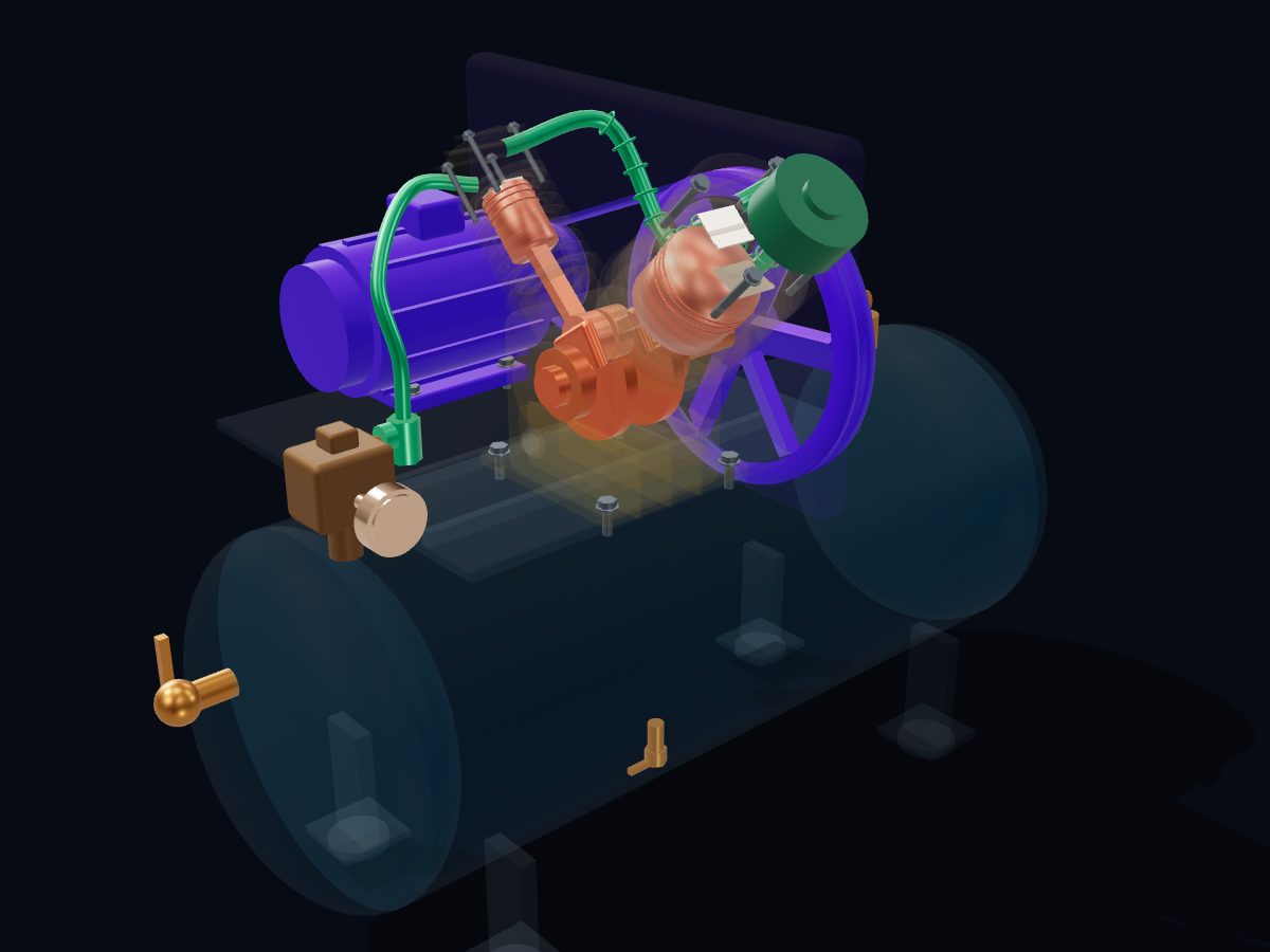 Reciprocating air compressorTwo-stage V-twin · 12 bar (175 psi) · 3.7 kWView and download →
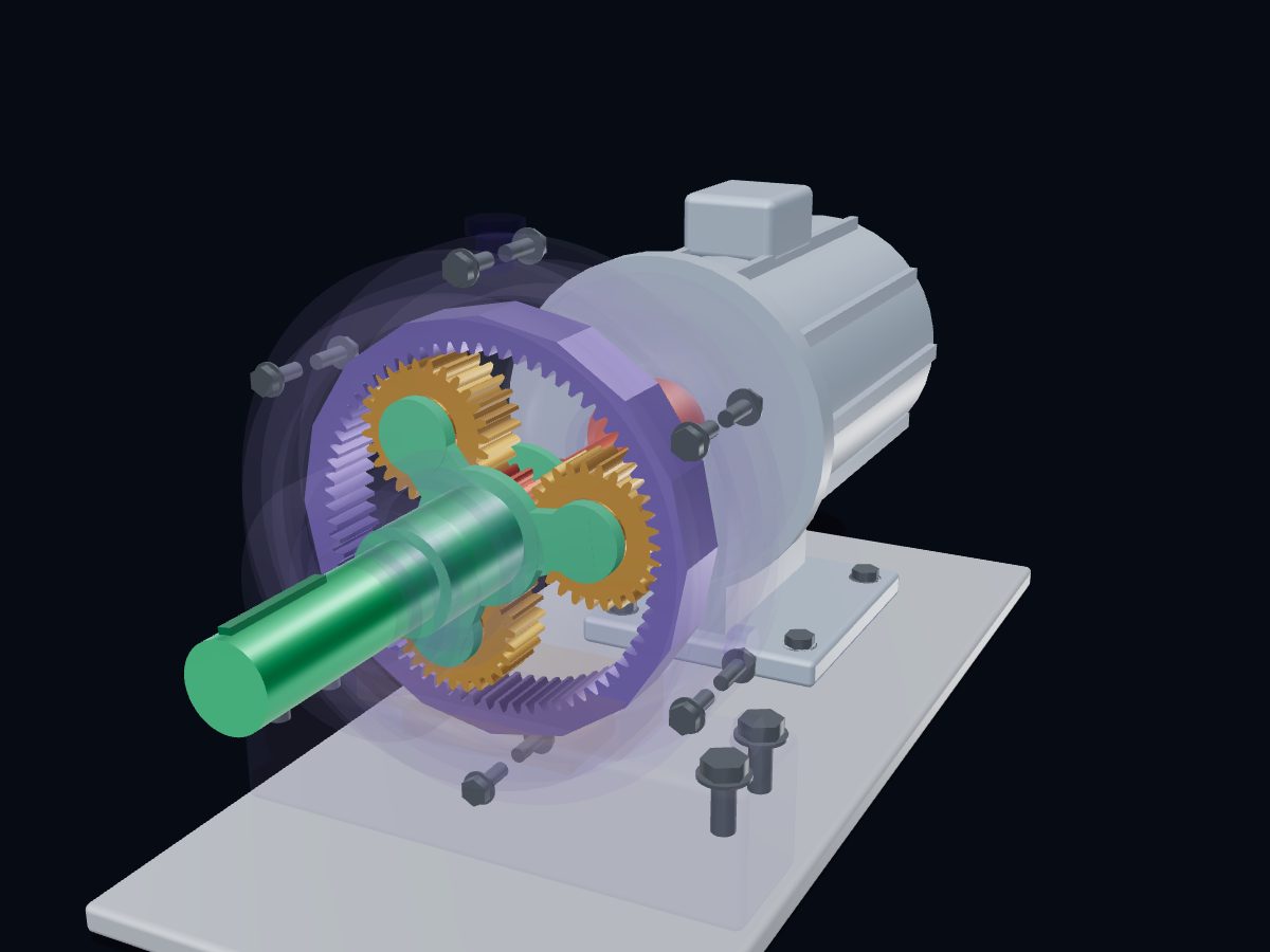 Planetary gearboxSun 18 · planets 3 × 27 · ring 72 · 5 : 1View and download →
All 3D models → · Live 3D atlas · Need an interactive 3D page for your own machine? Work with Engine‑X.