Engine‑X machine guide
How does a gear reducer work?
By Parth Parmar, mechanical design engineer · Updated
A gear reducer (gearbox) slows a motor down and multiplies its torque. A small gear on the fast input shaft drives a bigger gear on a slower shaft; the speed drops by the ratio of their tooth counts and the torque rises by almost the same factor. Two or more stages in series give big reductions.
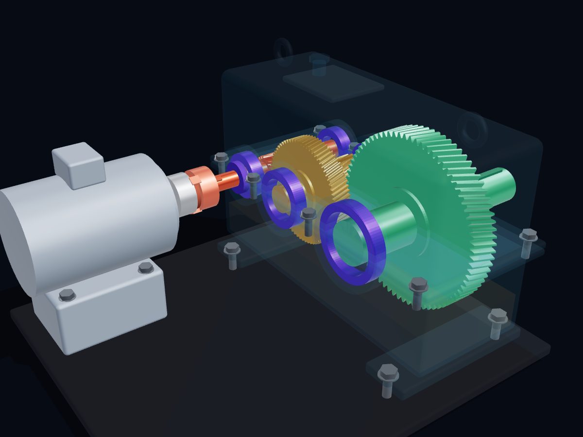
See it run: watch the input race and the output crawl, then explode, cut open and X‑ray the gearbox in 3D, free in your browser.
Open the 3D gear reducer →Or download the free 3D model (GLB, STL, AR).
Key facts
| Type in the 3D model | Two-stage parallel-shaft helical gear reducer |
|---|---|
| Ratio | 16 : 1 (4 : 1 × 4 : 1) |
| Speed | 1440 rpm in (4-pole motor, 50 Hz) → 90 rpm out |
| Torque | About 153 N·m out from a 1.5 kW motor |
| Gears | 18/72 teeth (module 2 mm) and 19/76 teeth (module 3 mm), 15° helix |
| Efficiency | In-line helical reducers: usually 95–98% |
| Bearings | Tapered roller, for radial load plus helical axial thrust |
| Lubrication | Splash: the output gear dips into the oil sump |
How it works, step by step
- The motor turns the input shaft at about 1440 rpm through a flexible jaw coupling.
- The 18-tooth pinion on the input shaft drives the 72-tooth gear: a 4 : 1 reduction, so the intermediate shaft turns at 360 rpm, the opposite way.
- The 19-tooth pinion on the intermediate shaft drives the 76-tooth output gear: another 4 : 1, so the output turns at 90 rpm.
- The second mesh reverses the direction again, so the output turns the same way as the motor.
- Torque rises at each stage by the ratio, minus a few percent lost to friction: about 153 N·m at the output.
- The helical teeth push the shafts along their axes; tapered roller bearings carry that thrust, and oil splashed by the output gear lubricates every mesh and bearing.
Main parts of a gear reducer
- Input shaft and pinion — the fast, low-torque side, coupled to the motor.
- Intermediate shaft — carries the big stage-1 gear and the small stage-2 pinion.
- Output gear and shaft — the slow, high-torque side that drives the machine.
- Bearings and oil seals — tapered roller bearings in each wall; lip seals where shafts leave the case.
- Housing — split cast-iron case that holds the shafts in line and forms the oil sump.
- Breather, sight glass and drain plug — let air out, show the oil level and catch wear particles.
How do you calculate gearbox ratio, output speed and torque?
Multiply the ratio of each stage, where each stage ratio is the driven gear's teeth divided by the driving gear's teeth. Divide the input speed by the total ratio to get the output speed. Output torque in N·m is 9550 × power in kW × efficiency ÷ output speed in rpm, so torque rises almost as much as speed falls.
| Stage 1 | 72 ÷ 18 = 4 : 1 |
|---|---|
| Stage 2 | 76 ÷ 19 = 4 : 1 |
| Total ratio | 4 × 4 = 16 : 1 |
| Output speed | 1440 ÷ 16 = 90 rpm |
| Output torque | 9550 × 1.5 × 0.96 ÷ 90 ≈ 153 N·m |
Gear sizes follow d = z × mn ÷ cos β for helical gears (KHK). Here the 18-tooth pinion is about Ø37 mm and the 76-tooth output gear about Ø236 mm.
What are the signs of a failing gearbox?
The warning signs are a new noise (whine, grinding, a knock once per turn), vibration that keeps rising, a case running hotter than usual, oil leaking at the seals or split line, and oil that looks dark, milky or full of metal. Most gearbox failures start with the oil, so check its level and condition first.
- Whine: usually tooth wear, wrong backlash, misalignment or thin oil.
- Grinding or rumble: bearing or tooth damage; take an oil sample and a vibration reading.
- Knock once per revolution: a chipped or broken tooth or a loose coupling; stop the drive.
- Heat: normal sumps run at about 54–82 °C; above about 93 °C suspect overload, poor cooling, wrong or too much oil.
- Leaking seals: worn lips, a scored shaft, or a blocked breather pressurising the case.
Is a helical gearbox more efficient than a worm gearbox?
Yes. Machine Design puts in-line helical reducers at 95–98% efficiency whatever the ratio, because helical teeth mostly roll against each other. Worm reducers slide, so they range from about 90% at 5 : 1 down to about 49% at 300 : 1. Worm boxes win on very high ratios in one compact stage and on cost; helical boxes win on efficiency and running cost.
Common questions
What is a gear reducer used for?
Anywhere a motor is too fast and too weak for the job: conveyors, mixers, cranes and hoists, pumps and fans that need slow speed, winches and machine tools.
Why use helical gears instead of spur gears?
Helical teeth engage gradually along the face, so they run quieter and carry more load than spur gears of the same size. The trade-off is axial thrust, which the bearings must carry.
Why does the output shaft turn the same way as the motor?
Every external gear mesh reverses direction. This reducer has two meshes, so the direction is reversed twice and the output turns the same way as the motor.
What does the breather on a gearbox do?
It lets air out as the gearbox warms up, so pressure does not build inside and push oil past the shaft seals. A blocked breather is a common cause of leaking seals.
How hot should an industrial gearbox run?
A typical sump runs at about 54–82 °C (130–180 °F) under normal load. Above about 93 °C (200 °F) usually means overload, poor cooling, the wrong oil or too much oil, and hot oil wears out fast.
Sources
References for the facts on this page, and further reading:
- KHK Gears — Gear guide: helical gears, pitch diameter and axial thrust
- Machine Design — Gear efficiency: key to lower drive cost
- Machine Design — What's the difference between spur, helical, bevel and worm gears?
- SDP/SI — Elements of metric gear technology: helical gears
- Malloy Electric — Gearbox troubleshooting field guide
Related reading on the blog
Spur, helical, bevel or worm? How to choose the right gear type · Ball, roller or journal bearing? How bearing types work
More machine guides
Compare: Belt vs chain vs gear drive: which is better?
How does a turbocharger work? · How does a centrifugal pump work? · How does a V-belt pulley drive work? · Turbocharger vs supercharger: what's the difference? · Centrifugal vs positive displacement pump: what's the difference? · How does a marine diesel engine work? · How does a plate heat exchanger work? · How does a reciprocating air compressor work? · How does a planetary gearbox work?
Need an interactive 3D page like this for your own machine? See Work with Engine‑X.