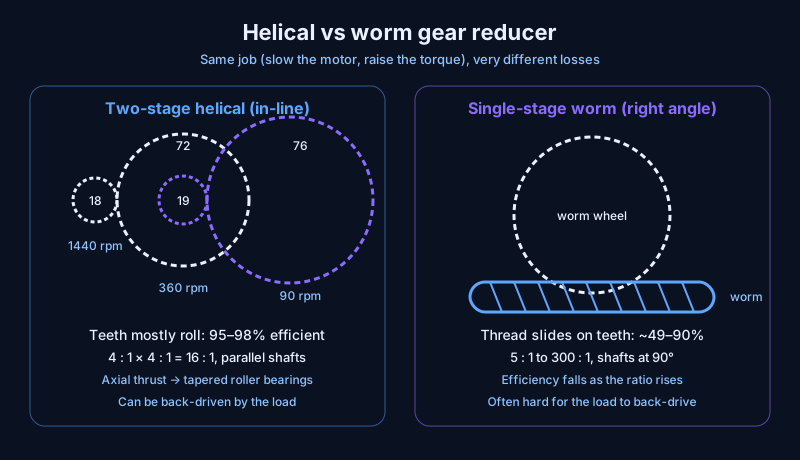
A helical gear reducer wastes far less power than a worm gear reducer. In-line helical units are usually 95–98% efficient whatever the ratio, while worm units run from about 90% at 5:1 down to about 49% at 300:1, because a worm's thread slides on the wheel instead of rolling. Worms win on big right-angle ratios in one compact stage.
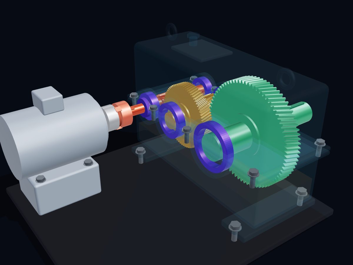
Both boxes do the same job: take a fast, weak motor and turn it into slow, strong output for a conveyor, mixer, hoist or pump. The difference is how the teeth meet, and that decides how much of the motor's power turns into heat instead of work. You can see the helical type running part by part in the new Engine-X gear reducer 3D model, and the step-by-step gear reducer guide covers the ratio and torque maths.
How does a helical gear reducer work?
A helical gear reducer passes power through pairs of gears on parallel shafts, and each pair reduces speed by the ratio of its tooth counts. A helical gear is a gear whose teeth are cut at an angle (the helix angle, typically 15–30° according to Machine Design) instead of straight across.
In the Engine-X model, the helical reducer works in two stages:
- An 18-tooth pinion on the motor shaft drives a 72-tooth gear: 4 : 1, so 1440 rpm becomes 360 rpm.
- A 19-tooth pinion on that intermediate shaft drives a 76-tooth gear: another 4 : 1, so the output turns at 90 rpm.
- Torque rises by almost the same 16 times, minus a few percent of friction.
Helical teeth mostly roll against each other and slide only a little, which is why the losses stay small. The angled teeth do push the shafts along their axes, so a helical box needs bearings that take axial thrust, such as tapered roller bearings; mating helical gears always have opposite hands (KHK, SDP/SI). Choosing between gear types in general is covered in Spur, helical, bevel or worm?.
How does a worm gear reducer work?
A worm gear reducer uses a screw (the worm) that turns a toothed wheel (the worm wheel) on a shaft at 90° to it. Each turn of a single-start worm moves the wheel by just one tooth, so a 40-tooth wheel gives 40 : 1 in a single stage.
That compact high ratio is the worm's big strength; Machine Design gives 5 : 1 to 300 : 1 as the typical range. The weakness is that the worm's thread slides across the wheel's teeth instead of rolling, and sliding friction turns input power straight into heat. The shallower the thread (the higher the ratio), the more it slides and the lower the efficiency.
Which is more efficient: helical or worm?
The helical gear reducer is more efficient, and the gap grows with the ratio. These are the figures from Machine Design's comparison of reducer types:
| Reducer type | Typical efficiency |
|---|---|
| In-line helical | 95–98%, regardless of ratio |
| Helical-bevel (right angle) | 94–97% |
| Worm, 5 : 1 single reduction | about 90% |
| Small worm units up to 30 : 1 | about 78% |
| Worm, 60 : 1 example unit | about 62% |
| Worm, 300 : 1 double reduction | about 49% |
The same article works through an example drive running 4,160 hours a year: the in-line helical unit saved $143 a year in electricity against a right-angle worm unit, and was also cheaper to buy. On a plant with dozens of drives running around the clock, that difference adds up fast.
When does a worm gear reducer still make sense?
A worm gear reducer still makes sense when its strengths matter more than its losses:
- Very high ratio, one small box. 50 : 1 or more at a right angle without a second stage.
- Right-angle output. The shafts are already at 90°, which suits many conveyors and machine layouts. (A helical-bevel box also turns 90°, at 94–97%.)
- Hard to back-drive. With a shallow worm angle, friction stops the wheel from turning the worm, which Machine Design notes can act as a stop on a conveyor. It is not a guaranteed brake, so a hoist still needs a real brake.
- Short or occasional running. If the drive only runs a few minutes an hour, wasted energy matters less than price and size.
For a drive that runs all day, a helical or helical-bevel reducer is almost always the better choice, because the lost power in a worm box is paid for every hour and comes out as heat the oil has to carry away.
The engineering takeaway
Gear reducers are judged by how their teeth meet. Rolling helical teeth keep 95–98% of the power; a sliding worm thread can lose half of it at high ratios. Use a worm when you need a big right-angle ratio in one compact, hard-to-back-drive stage; use helical (or helical-bevel) when the drive runs long hours and efficiency pays. To see helical gears meshing, explode the 3D gear reducer, and compare other drives in belt vs chain vs gear drive.