By Parth Parmar, mechanical design engineer · 47 pieces, 22 parts · Updated
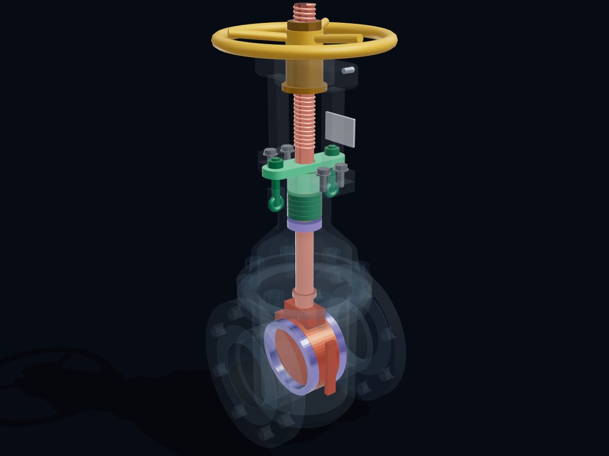
A gate valve opens and closes a pipe by sliding a flat gate (the wedge) across it. Turning the handwheel winds a threaded stem that lifts the wedge clear of the bore, so flow passes straight through; turning it back pushes the wedge down between two seat rings to shut the line tight.
Single parts: scroll to the parts list. These are learning models, not a print kit: some parts touch or overlap and there are no fit tolerances.
Free for personal and educational use under CC BY-NC 4.0. Credit “Engine-X by Parth Parmar (engx3d.com)” when you share or remix it. Don’t sell the files or prints. For commercial use, get in touch. Every file carries the Engine-X mark and a hidden digital fingerprint that identifies it.
Key facts
Machine
NPS 4 Class 150 · OS&Y rising stem · 18 turns to open
Parts modeled
47 named parts in 6 systems (22 different parts to download)
Model size
254 × 652 × 254 mm (real scale)
Formats
GLB (glTF 2.0) 3.4 MB, STL 2.4 MB, USDZ for iPhone AR, ZIP of part STLs 0.5 MB
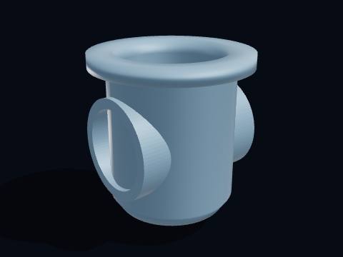
6 parts: Cast-steel body with flanged ends, bonnet, gasket and the bonnet studs: the pressure-holding shell.
Seats
2 parts: The two hard-faced seat rings and the backseat bushing.
Wedge & stem
2 parts: The wedge and the rising stem that lifts it: the parts that open and close the bore.
Stem seal
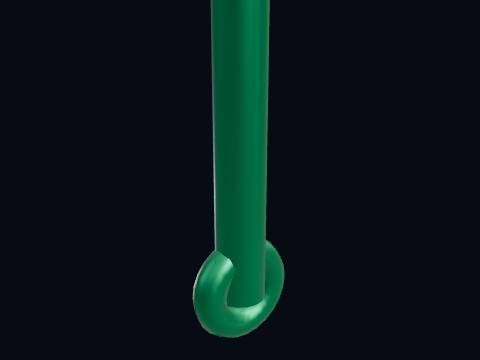
5 parts: Packing rings, gland, gland flange, eye bolts and nuts: the seal where the stem leaves the valve.
Yoke
4 parts: The yoke frame, its bolts, the grease fitting and the nameplate.
Handwheel & yoke nut
3 parts: Handwheel, yoke nut and handwheel nut: they turn, but never rise.
All 22 parts of the gate valve, one by one
Every part with a picture, what it does and its own STL file: valve body, end flange, bonnet, bonnet gasket, bonnet stud, bonnet nut, seat ring, backseat bushing and more. Open any part in the live 3D atlas to see where it sits and how it moves. A part used several times (valves, bolts) is shown once with its count.
Cast-steel body with flanged ends, bonnet, gasket and the bonnet studs: the pressure-holding shell.
Valve body
The valve body, the main pressure-holding casting. Its two flanged ends bolt into the pipeline, and between them it holds the seat rings and the cavity the wedge rises into. Face to face it measures 229 mm, the ASME B16.10 length for a NPS 4 Class 150 gate valve.
More about this part
Class 150 cast carbon steel (ASTM A216 WCB) is rated 19.6 bar (285 psig) at ambient temperature under ASME B16.34; the rating falls as the temperature rises.
Drawn see-through so the wedge and seats stay visible.
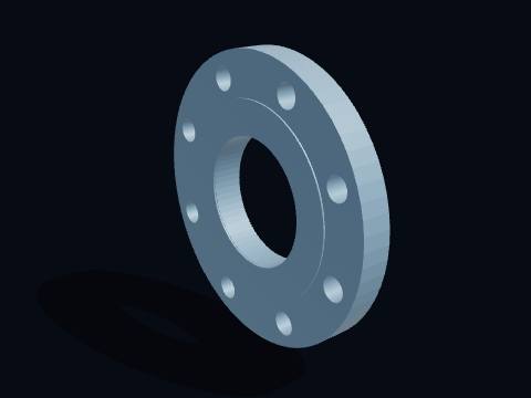
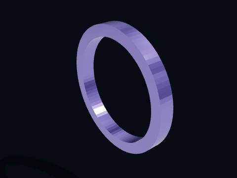
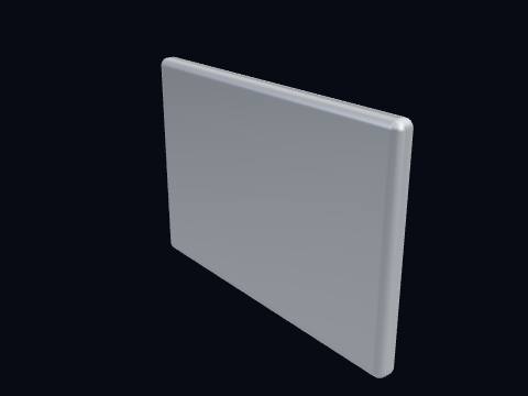
An end flange with a raised face, cast as one piece with the body. Its eight 5/8-inch bolts on a 190.5 mm circle line up with a standard ASME B16.5 NPS 4 Class 150 pipe flange, so any make of valve fits the same gap in the pipe.
The bonnet, the cover bolted on top of the body. It closes the cavity the wedge rises into and carries the stuffing box where the packing seals the stem.
More about this part
A bolted bonnet can be removed to reach the wedge and seats without taking the valve out of the line.
The bonnet gasket seals the bolted joint between the valve body and the bonnet. It seals the joint between the body and the bonnet, which sees the full line pressure.
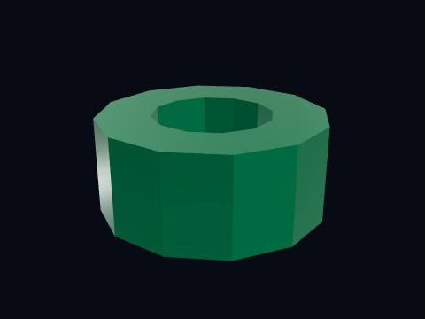
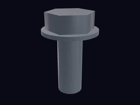
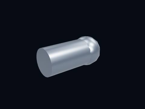
A bonnet stud is one of the threaded rods that hold the bonnet on the valve body. Eight of them clamp the bonnet onto the body and squeeze the gasket; they are tightened evenly in a star pattern.
The two hard-faced seat rings and the backseat bushing.
Seat ring ×2
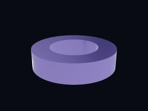
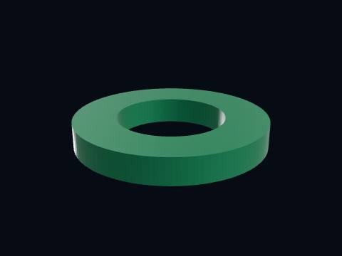
A seat ring, welded or screwed into the body on each side of the wedge. The wedge faces press against these two rings to shut off the flow, so their sealing faces are hard-faced to resist wear and scoring.
More about this part
Seats are often A105 steel with a Stellite 6 hard facing.
Its face leans 5° from vertical in this model, matching the taper of the wedge.
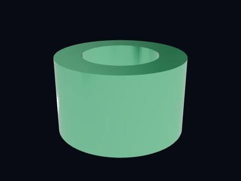
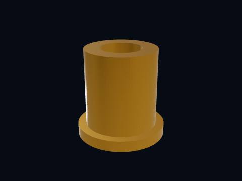
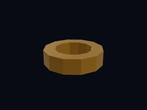
The backseat bushing, a hard ring at the bottom of the stuffing box. When the valve is fully open the stem collar presses up against it and seals the stem from the inside, a second seal behind the packing.
More about this part
The backseat is meant as a back-up seal. Repacking under pressure while relying on it is something most operators avoid.
The wedge and the rising stem that lifts it: the parts that open and close the bore.
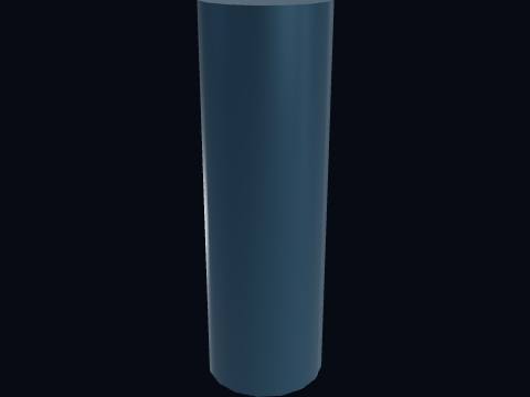
Stem
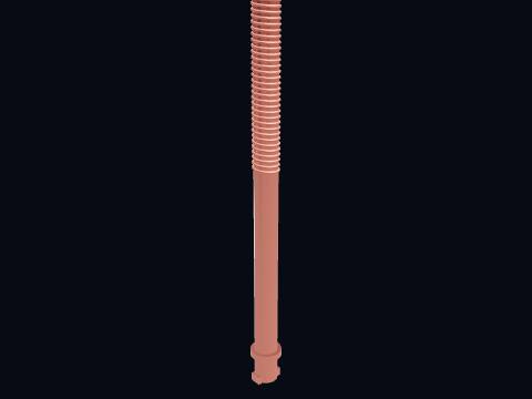
The stem, a 470 mm steel rod joining the handwheel to the wedge. Its upper part carries a trapezoidal (Acme) thread that runs through the yoke nut; its lower end has a T-head that hooks into a slot on top of the wedge. In an OS&Y valve the stem rises without turning, so its height shows at a glance whether the valve is open.
More about this part
The thread sits outside the valve, away from the process fluid, so it can be greased and does not corrode or clog.
A collar on the stem seats against the backseat bushing when the valve is fully open.
The wedge (gate), the part that actually closes the valve. It slides down across the full bore and its two tapered faces jam against the seat rings; turning the handwheel the other way lifts it 108 mm, clear of the bore, so the flow passes straight through.
More about this part
A gate valve is an on/off valve: half open, the fast flow under the wedge erodes the seats and the wedge vibrates. For throttling, use a globe valve.
The taper means seat wear is taken up by the wedge going a little lower, so the valve keeps sealing.
Packing rings, gland, gland flange, eye bolts and nuts: the seal where the stem leaves the valve.
Packing ring ×5
A packing ring is one of the soft graphite rings that seal around the valve stem. A stack of these soft graphite rings fills the stuffing box around the stem; squeezed by the gland, they press against the stem and stop the line fluid from leaking out where the stem leaves the valve.
More about this part
A small stem leak can usually be stopped by tightening the gland nuts a little, evenly on both sides.
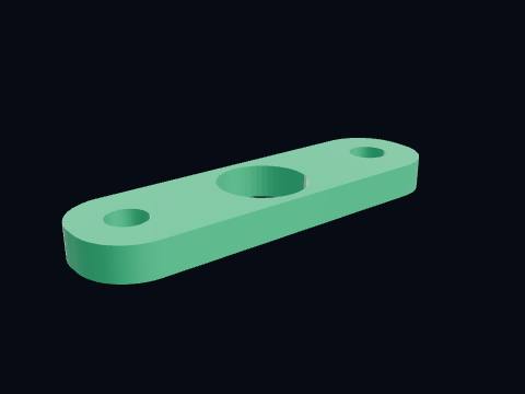
The gland flange presses the packing rings down around the stem. Two eye bolts pass through its ends; tightening their nuts pushes the gland down onto the packing.
A gland eye bolt pulls the gland flange down onto the packing. It pivots on a pin in a lug on the bonnet, so it can be swung out of the way when the packing is changed.
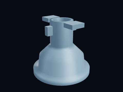
The yoke frame, its bolts, the grease fitting and the nameplate.
Yoke
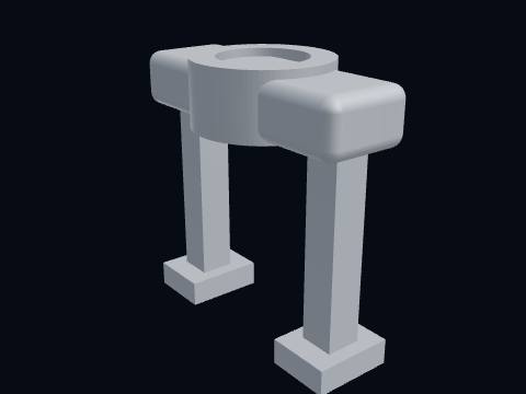
The yoke, the open frame on top of the bonnet. It holds the yoke nut and handwheel at a fixed height, so turning the handwheel can only push the stem up or pull it down. The stem thread stays outside, between its arms.
More about this part
OS&Y means outside screw and yoke: the screw thread is outside the valve body, carried by this yoke.
The grease fitting on the yoke head is where the yoke nut is lubricated. Grease pumped in here lubricates the yoke nut thread and its bearing faces, which keeps the handwheel easy to turn.
The nameplate, riveted to the yoke, identifies the valve. It carries the size, pressure class, body and trim materials, standard and serial number, which is what a fitter checks against the line list before fitting a valve.
Handwheel, yoke nut and handwheel nut: they turn, but never rise.
Yoke nut
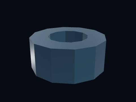
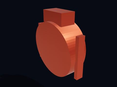
The yoke nut (stem nut) is the threaded nut in the yoke head that drives the stem up and down. It turns with the handwheel but cannot move up or down, so its internal thread drives the stem: with a 6 mm lead, 18 turns of the handwheel take the wedge from fully shut to fully open.
More about this part
Made of a different metal from the stem (here a nickel-alloy ductile iron) so the two threads do not gall together.
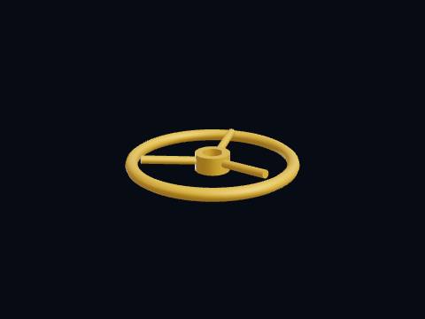
The handwheel, Ø254 mm, is what the operator turns to open and close the gate valve. Turned clockwise it closes the valve and anticlockwise it opens it. It is keyed to the yoke nut, so it never rises with the stem.
More about this part
Never use a bar or a wheel key on the rim to force a stuck valve: that bends the stem and wrecks the seats.
Yes. The gate valve 3D model is free for personal and educational use under CC BY-NC 4.0: credit "Engine-X by Parth Parmar (engx3d.com)". Selling the files or prints, or other commercial use, needs written permission.
Which file formats is the gate valve 3D model in?
GLB (glTF 2.0) with colours and named parts, STL in millimetres (Z-up) for CAD, slicers and 3D printing, USDZ for AR on iPhone, and a ZIP with all 22 parts as separate STL files.
How many parts does the gate valve 3D model have?
47 named pieces in 6 systems (body & bonnet, seats, wedge & stem, stem seal, yoke, handwheel & yoke nut). Repeated pieces such as bolts are folded together, which leaves 22 different parts, each one downloadable on its own.
Can I 3D print the gate valve model?
Yes, download the STL (whole machine or single parts) and open it in your slicer. It is a learning model at real scale, not a print kit: some parts touch or overlap and there are no fit tolerances, so scale it and print parts one by one.
How do I see the gate valve in AR on my phone?
Tap "View in your room" on this page. Android opens Google Scene Viewer and iPhone opens AR Quick Look, both without an app, and you can place the model at real size on the floor or a table.
Can I see the gate valve working in 3D?
Yes. Tap "Play live 3D here" or open the Engine-X atlas (engx3d.com/atlas#m=gatevalve): it runs in the browser with true motion, and you can explode it, cut it open and X-ray it.
How to credit or cite this model
Credit line: Gate valve 3D model, Engine-X by Parth Parmar (engx3d.com)
Citation: Parmar, P. (2026). Gate valve 3D model [3D model, CC BY-NC 4.0]. Engine-X. https://engx3d.com/3d-models/gate-valve
Used this model?
For a class, a project, a print or a video? Tell us how it went. With your OK, we may feature your work here.
 Open full screen →
 View in your room · AR