By Parth Parmar, mechanical design engineer · 112 pieces, 39 parts · Updated
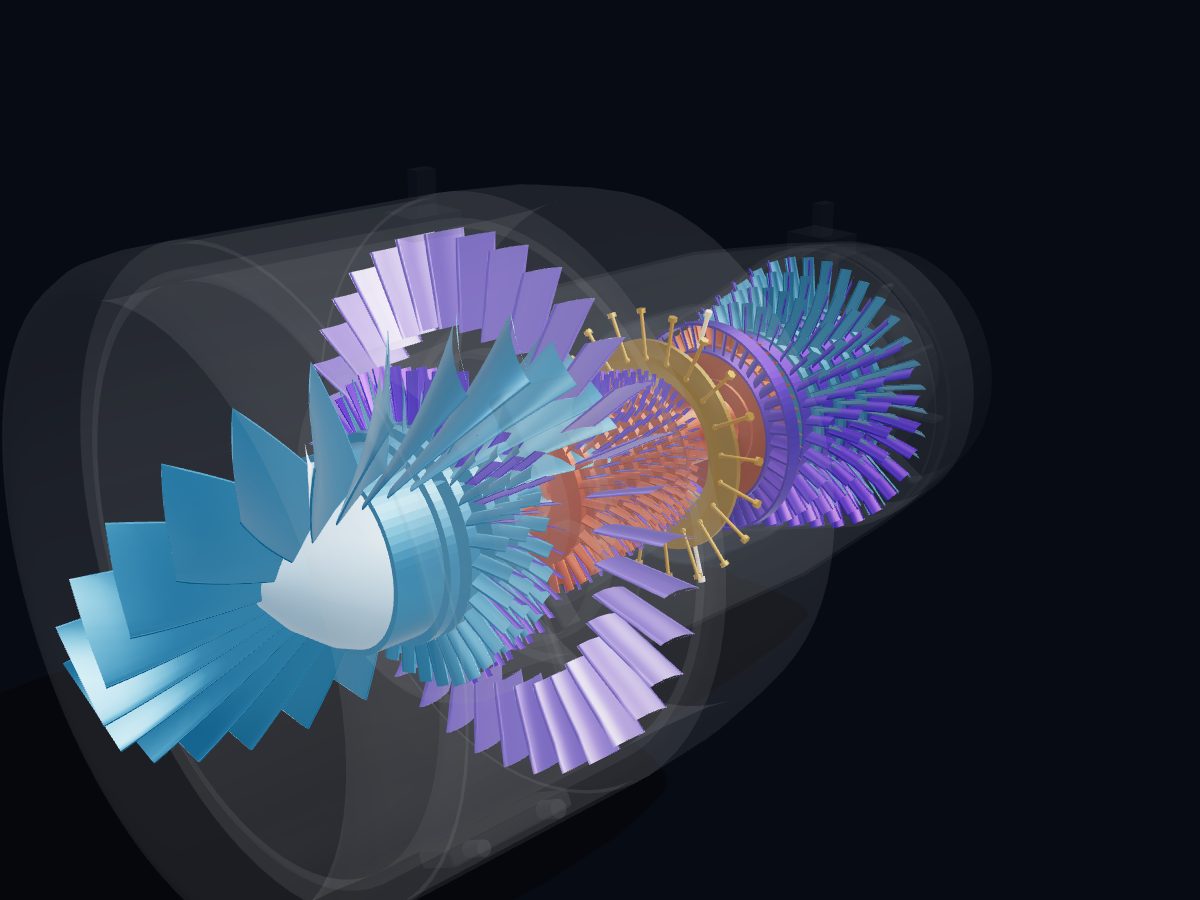
A turbofan jet engine has a big fan at the front driven by a gas turbine core. The core squeezes part of the air, burns fuel in it and uses the hot gas to spin turbines that drive the compressor and fan. Most of the air bypasses the core, and that cool, slower bypass stream gives most of the thrust.
Single parts: scroll to the parts list. These are learning models, not a print kit: some parts touch or overlap and there are no fit tolerances.
Free for personal and educational use under CC BY-NC 4.0. Credit “Engine-X by Parth Parmar (engx3d.com)” when you share or remix it. Don’t sell the files or prints. For commercial use, get in touch. Every file carries the Engine-X mark and a hidden digital fingerprint that identifies it.
Key facts
Machine
CFM56-7B style · 61 in fan · two spools · N2 ≈ 2.8 × N1
Parts modeled
112 named parts in 6 systems (39 different parts to download)
Model size
3341 × 1865 × 1768 mm (real scale)
Formats
GLB (glTF 2.0) 8.7 MB, STL 6.4 MB, USDZ for iPhone AR, ZIP of part STLs 0.7 MB
6 parts: Fan, spinner, booster rotors, LP shaft and the four LP turbine rotors: all turn together.
High-pressure spool (N2)
3 parts: Nine HP compressor rotors, the HP shaft and the HP turbine: the core spool, about 2.8 times faster.
Stator vanes
5 parts: Fixed vane rows: fan outlet guide vanes, booster and HPC stators, turbine nozzles.
Combustor
5 parts: Annular combustor: dome, liners, fuel nozzles and igniters.
Casings, frames & bearings
10 parts: Fan frame, compressor, combustion and turbine cases, rear frame, exhaust, main bearings.
Nacelle & accessories
10 parts: Inlet, fan case and cowls, reverser cowl, core cowl, accessory gearbox, FADEC and mounts.
All 39 parts of the turbofan jet engine, one by one
Every part with a picture, what it does and its own STL file: low-pressure shaft, spinner, fan disk, fan blade, booster rotor stage, lpt rotor stage, high-pressure shaft, hpc rotor stage and more. Open any part in the live 3D atlas to see where it sits and how it moves. A part used several times (valves, bolts) is shown once with its count.
Fan, spinner, booster rotors, LP shaft and the four LP turbine rotors: all turn together.
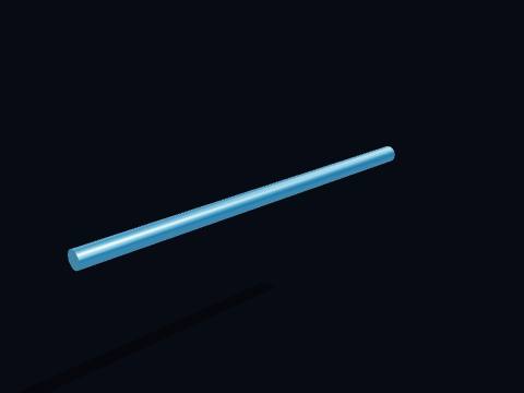
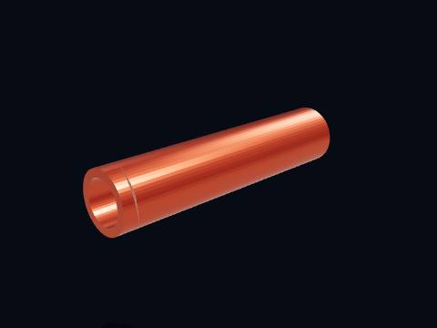
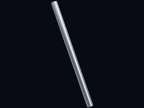
Low-pressure shaft
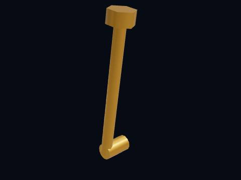
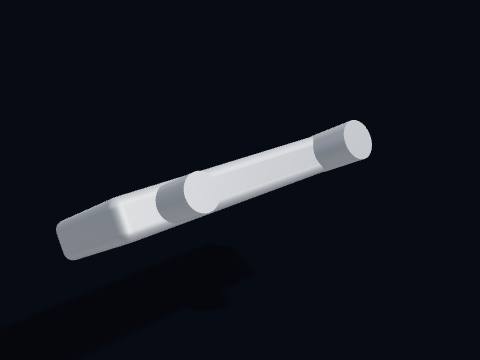
The low-pressure shaft connects the low-pressure turbine at the back to the fan at the front. It runs the full length of the engine, inside the HP shaft, and drives the fan and booster at up to 5382 rpm.
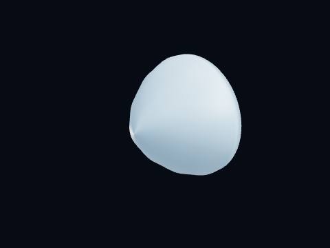
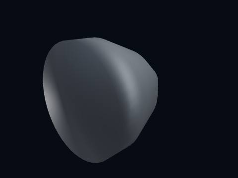
The spinner is the cone at the very front of the turbofan engine. It smooths the air onto the roots of the fan blades and sheds ice; the swirl painted on many spinners lets ground crew see at a glance that the fan is turning.
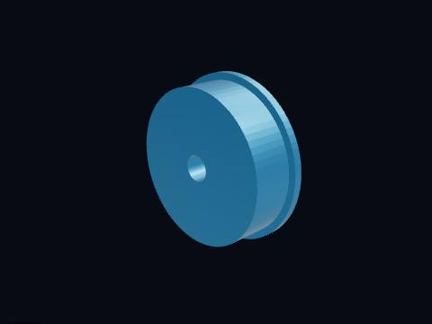
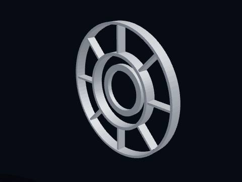
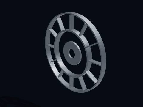
The fan disk, the hub that carries the fan blades in dovetail slots round its rim. It is bolted to the low-pressure shaft, which the low-pressure turbine drives.
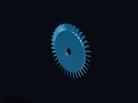
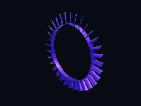
A fan blade is one of the large front blades that move most of the air through the turbofan. The 24 wide-chord titanium blades of this 61-inch fan move most of the air through the engine; most of it bypasses the core and gives most of the thrust.
More about this part
The blade twists from root to tip because the tip moves much faster than the root.
A fan blade is the part of the engine most at risk from bird strikes, so each blade design must pass a bird-ingestion test before the engine is certified.
A booster (low-pressure compressor) rotor stage. The booster sits right behind the fan on the same low-pressure shaft and gives the core air a first squeeze before the high-pressure compressor.
More about this part
Three booster stages in the CFM56-7B (EASA TCDS E.004).
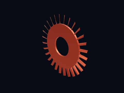
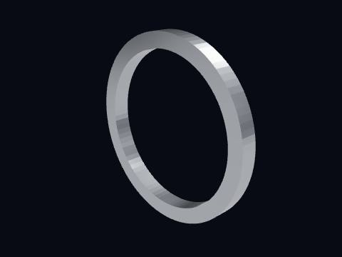
A low-pressure turbine (LPT) rotor stage, one of four. The gas leaving the HP turbine still has plenty of energy; the four LPT stages take it out and turn the low-pressure shaft that drives the fan.
More about this part
The LPT gets bigger towards the back because the gas expands as it gives up pressure.
Nine HP compressor rotors, the HP shaft and the HP turbine: the core spool, about 2.8 times faster.
High-pressure shaft
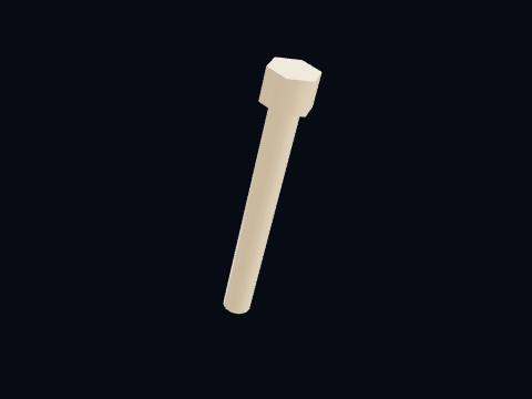
The high-pressure shaft (core spool) joins the HP turbine to the HP compressor. It turns at up to 15183 rpm. It is a hollow tube; the low-pressure shaft runs through the middle of it.
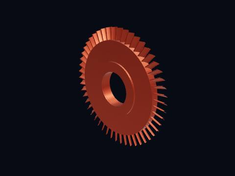
A high-pressure compressor (HPC) rotor stage, one of nine on the high-pressure shaft. Each stage raises the pressure a little; together with the fan and booster the engine squeezes the air about 32 times before it burns fuel.
More about this part
The blades get shorter stage by stage, because squeezed air takes less room.
The HPC turns about 2.8 times faster than the fan.
The high-pressure turbine (HPT) rotor, a single stage that drives the whole high-pressure compressor. Its blades work in gas far hotter than their own melting point; air bled from the compressor flows through tiny holes inside each blade to cool it.
More about this part
Single-crystal nickel blades with thermal barrier coatings (CFM).
Exhaust gas temperature (EGT) is limited to 950 °C displayed at take-off (EASA TCDS E.004).
Fixed vane rows: fan outlet guide vanes, booster and HPC stators, turbine nozzles.
Fan outlet guide vanes
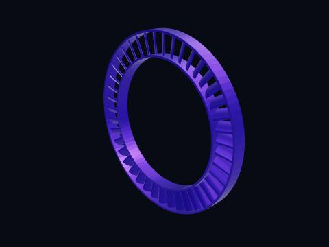
The fan outlet guide vanes (OGVs), a ring of fixed vanes in the bypass duct behind the fan. The fan leaves the air swirling; these vanes straighten it so it leaves the nozzle straight back and gives the most thrust.
A booster stator, a fixed ring of vanes between booster rotor stages. Each stator turns the swirling flow from the rotor ahead of it into pressure and lines the air up for the next rotor.
A high-pressure compressor stator, the fixed vane row after each rotor. The front stators of a high-pressure compressor can turn on their own pivots (variable stator vanes) to keep the airflow stable at low speed.
The high-pressure turbine nozzle (NGV), fixed vanes at the combustor exit. They speed up the hot gas and turn it to hit the turbine blades at the right angle. They run in the hottest gas in the engine.
Annular combustor: dome, liners, fuel nozzles and igniters.
Combustor dome
The combustor dome, the front wall of the combustion chamber. It holds the swirlers where each fuel nozzle sprays fuel into fast-swirling air, which keeps the flame short and stable.
The outer liner of the annular combustor forms the outside wall of the chamber where the fuel burns. The combustor is one ring-shaped chamber running all round the engine; rows of holes in its liners let in air to burn the fuel, then cool the gas before it reaches the turbine.
More about this part
Most of the air from the compressor does not burn: it cools the liners and dilutes the hot gas.
A fuel nozzle sprays fuel into the combustor as a fine mist. Fuel metered by the FADEC is sprayed through these nozzles into the combustor dome as a fine mist that mixes with air and burns continuously.
An igniter plug, the jet engine's spark plug. It only sparks while starting (or in heavy rain and icing as a precaution); once lit, the flame keeps itself going.
Fan frame, compressor, combustion and turbine cases, rear frame, exhaust, main bearings.
Fan frame
The fan frame, the main structural ring at the front of the core. Its struts hold the core and the fan case together and carry the forward bearings; one strut houses the radial drive shaft to the accessory gearbox.
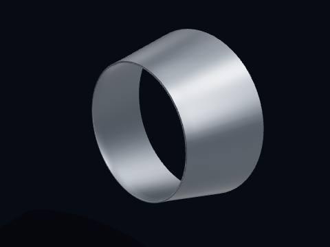
The splitter and booster case divides the fan air between the bypass duct and the core. Its sharp front edge divides the air from the fan: the outer part goes down the bypass duct, the inner part into the core. In this engine family that split is about 5 to 1.
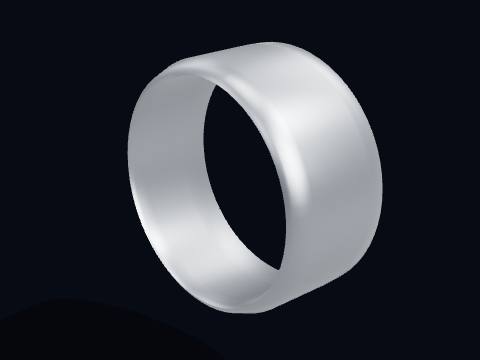
The high-pressure compressor case, the casing round the nine HPC stages. The gap between it and the blade tips is kept tiny, because air leaking over the tips is lost efficiency.
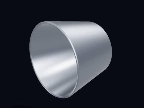
The core exhaust nozzle is the rear outlet where the hot core gas leaves the engine. The hot core gas leaves here, at a few hundred degrees and high speed; it gives a smaller share of the thrust than the bypass air.
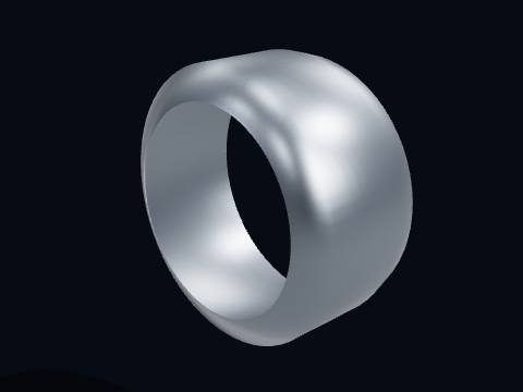
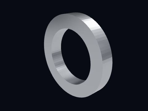
A main shaft bearing supports one of the two engine spools as it spins. Ball bearings take the axial thrust of each spool; roller bearings carry the radial load. They sit in oil-sealed sumps fed by the engine's own oil system.
A main shaft bearing supports one of the two engine spools as it spins. Ball bearings take the axial thrust of each spool; roller bearings carry the radial load. They sit in oil-sealed sumps fed by the engine's own oil system.
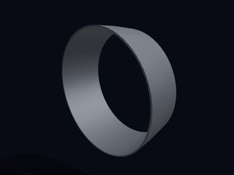
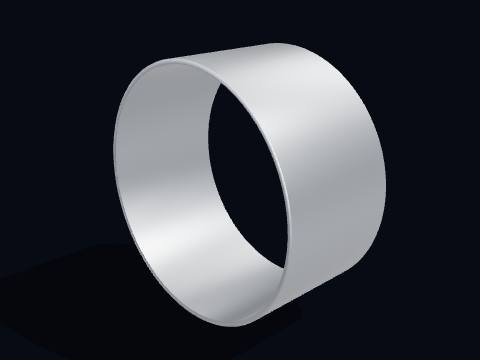
The fan case, the strong metal ring round the fan. It is designed to contain a released fan blade, which is demonstrated in a blade-off test before certification.
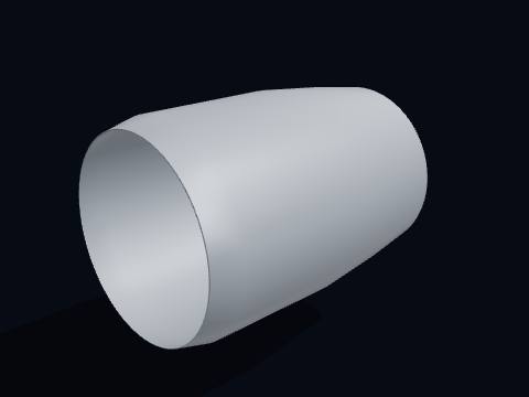
The inlet cowl (air intake) is the front ring of the nacelle that feeds air to the fan. Its rounded lip guides air smoothly into the fan at any flight attitude; in flight it is de-iced with hot air bled from the engine.
The thrust reverser cowl, the rear part of the nacelle round the bypass duct. On landing it slides back and blocker doors turn the bypass air forward through cascades to help slow the aircraft (the reverser internals are not modelled).
The accessory gearbox drives the pumps and generator of the engine from the HP shaft. Driven by the HP shaft through the radial drive shaft, it runs the fuel pump, oil pumps, hydraulic pump and electrical generator, and the starter turns the engine through it.
The FADEC (full authority digital engine control) unit. It sets the fuel flow, compressor variable geometry and more from the pilot's thrust lever and engine sensors; it has two independent channels (EASA TCDS E.004).
An engine mount, where the engine hangs from the wing pylon. The forward mount takes the thrust and the aft mount the vertical and side loads, in this layout.
An engine mount, where the engine hangs from the wing pylon. The forward mount takes the thrust and the aft mount the vertical and side loads, in this layout.
Is the turbofan jet engine 3D model free to download?
Yes. The turbofan jet engine 3D model is free for personal and educational use under CC BY-NC 4.0: credit "Engine-X by Parth Parmar (engx3d.com)". Selling the files or prints, or other commercial use, needs written permission.
Which file formats is the turbofan jet engine 3D model in?
GLB (glTF 2.0) with colours and named parts, STL in millimetres (Z-up) for CAD, slicers and 3D printing, USDZ for AR on iPhone, and a ZIP with all 39 parts as separate STL files.
How many parts does the turbofan jet engine 3D model have?
112 named pieces in 6 systems (low-pressure spool (n1), high-pressure spool (n2), stator vanes, combustor, casings, frames & bearings, nacelle & accessories). Repeated pieces such as bolts are folded together, which leaves 39 different parts, each one downloadable on its own.
Can I 3D print the turbofan jet engine model?
Yes, download the STL (whole machine or single parts) and open it in your slicer. It is a learning model at real scale, not a print kit: some parts touch or overlap and there are no fit tolerances, so scale it and print parts one by one.
How do I see the turbofan jet engine in AR on my phone?
Tap "View in your room" on this page. Android opens Google Scene Viewer and iPhone opens AR Quick Look, both without an app, and you can place the model at real size on the floor or a table.
Can I see the turbofan jet engine working in 3D?
Yes. Tap "Play live 3D here" or open the Engine-X atlas (engx3d.com/atlas#m=turbofan): it runs in the browser with true motion, and you can explode it, cut it open and X-ray it.
How to credit or cite this model
Credit line: Turbofan jet engine 3D model, Engine-X by Parth Parmar (engx3d.com)
Citation: Parmar, P. (2026). Turbofan jet engine 3D model [3D model, CC BY-NC 4.0]. Engine-X. https://engx3d.com/3d-models/turbofan-engine
Used this model?
For a class, a project, a print or a video? Tell us how it went. With your OK, we may feature your work here.
 Open full screen →
 View in your room · AR