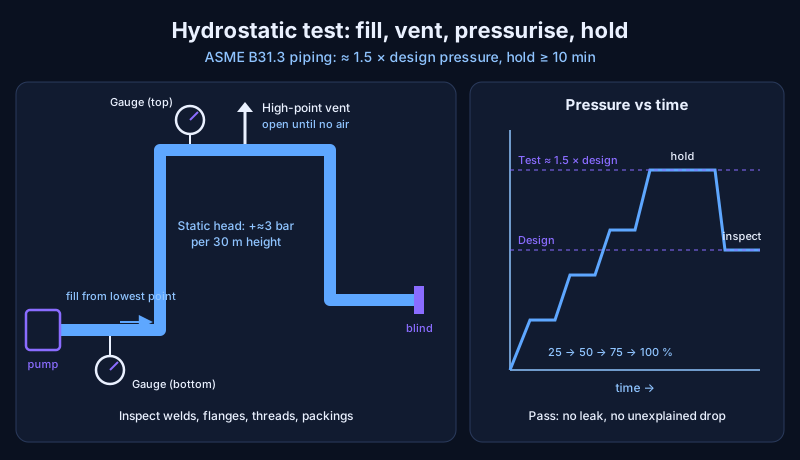
A hydrostatic test is a pressure test in which a pipe system, vessel or valve is filled with water and pressurised above its design pressure to prove it is strong enough and does not leak. For ASME B31.3 process piping, the test pressure is about 1.5 times the design pressure.
The pressure is held for at least 10 minutes while every weld, flange and joint is inspected.
Hydrotesting is the last check before new or repaired piping goes into service — in refineries, power plants, water lines and ship systems alike. It catches bad welds, loose flanges, cracked fittings and wrong gaskets while the system is full of harmless water, instead of oil, steam or gas.
What does a hydrostatic test prove?
A hydrostatic test proves two things at once: strength and tightness. Raising the pressure above design shows the pipe, welds and fittings can carry more than their working load without bursting or permanently deforming. Holding that pressure shows the system does not leak at any joint.
The test does not prove the system will last forever. It does not find slow corrosion or fatigue cracks that have not yet gone through the wall. That is why hydrotesting works alongside other checks such as visual inspection, radiography and ultrasonic thickness gauging.
What pressure is used for a hydrostatic test?
The hydrostatic test pressure for process piping under ASME B31.3 is at least 1.5 × design pressure, multiplied by a temperature correction. Project Materials explains the formula:
Test pressure = 1.5 × design pressure × (S_t ÷ S_d)
- S_t is the allowable stress of the material at test temperature (usually ambient).
- S_d is the allowable stress at the design temperature.
For carbon steel near room temperature the ratio is about 1.0, so the test is simply 1.5 × design. For a line designed to run hot, the material is weaker at design temperature, so the ratio is bigger than 1 and the cold test pressure goes up. Two limits apply:
- The weakest component. The test pressure must not exceed the rating of any part in the test, which is often the flanges.
- Static head. Water weight adds pressure at low points. Project Materials notes that a 30 m height difference adds about 3 bar at the lowest point, so the low-point gauge reads higher than the top.
Pressure vessels built to ASME Section VIII, Division 1 use a lower factor of 1.3 × MAWP (maximum allowable working pressure), also corrected for temperature.
| Code | What it covers | Hydrotest pressure | Minimum hold |
|---|---|---|---|
| ASME B31.3 | Process piping | 1.5 × design × S_t/S_d | 10 minutes |
| ASME VIII Div. 1 | Pressure vessels | 1.3 × MAWP × stress ratio | Per code/spec |
| ASME B31.4 / B31.8 | Long pipelines | Per code | Typically 4–24 hours |
How is a hydrostatic test done, step by step?
A hydrostatic test is done in a fixed order that keeps air out and pressure under control. The steps below follow Project Materials' procedure:
- Prepare the system. Fit test blinds on all open ends, isolate equipment that must not see test pressure, and install at least two calibrated gauges — one at the highest point and one at the lowest. Set up a chart recorder and a safety perimeter.
- Fill from the lowest point. Keep the high-point vents open until water flows out steadily with no air. Trapped air is the biggest hazard in a hydrotest.
- Close the vents and pressurise in steps. Raise pressure to about 25%, 50%, 75% and then 100% of test pressure, holding about 5 minutes at each step to check for leaks and let the system settle.
- Hold at test pressure. ASME B31.3 requires at least 10 minutes; many project specifications ask for 30 minutes to 1 hour after the pressure is stable. Record pressure and temperature.
- Drop to design pressure and inspect. Walk the whole system and check every weld, flange, threaded joint and valve packing.
- Depressurise slowly and drain. Vent through a controlled valve, then drain the low points and blow them out with air or nitrogen.
- Document. Record the test pressure, hold time, chart, results and sign-offs.
On the job, step 2 is where most time goes. A long line with many high points needs every vent opened and watched — a pocket of air left in the pipe both spoils the test and stores dangerous energy.
How do you know if a hydrostatic test has passed?
A hydrostatic test passes when there is no visible leak and no unexplained pressure drop during the hold. Project Materials lists the failure signs: any leak, seepage, weeping or deformation, or a pressure fall that cannot be explained by temperature change. Both gauges should agree, and the chart should show a flat line at test pressure.
Temperature matters more than people expect. Project Materials notes that a 1 °C change in water temperature can shift pressure by 1–3 bar in a rigid system. A line that warms up in the sun will show rising pressure; one that cools in the evening will show a drop that looks like a leak. That is why the pressure is allowed to stabilise and temperature is recorded alongside it.
Why is water used instead of air for pressure testing?
Water is used instead of air because it is almost incompressible, so it stores very little energy under pressure. If a weld fails during a hydrotest, the result is a drip or a spray.
Compressed air or gas stores a large amount of energy, and Araner notes that pneumatic testing carries the hazard of that energy being released suddenly — a failure can throw fragments.
For that reason, pneumatic testing is used only where water cannot be — for example, systems that must stay completely dry. Under B31.3 it runs at a lower 1.1 × design pressure, with a relief valve and extra safety distance.
Water quality also matters. Project Materials recommends chlorides below 50 ppm for 300-series stainless steel (and below 25 ppm for duplex), because chlorides left in a stainless line can cause pitting and stress corrosion cracking. Stainless systems should be drained and dried promptly after the test.
The engineering takeaway
A hydrostatic test is simple in principle — fill, vent, pressurise, hold, inspect — but each step has a reason: the 1.5 factor proves margin, the temperature correction accounts for hot service, the high-point vents remove stored energy, and the hold time with two gauges separates real leaks from temperature effects. Done properly, it is the cheapest insurance a piping system can get. Once the line is in service, the next threat is the slow kind — see how sea-water cooling equipment is protected and maintained. Most systems tested this way are full of valves and welded joints, so see the gate, globe, butterfly and check valve guide and welding types and NDT inspection.
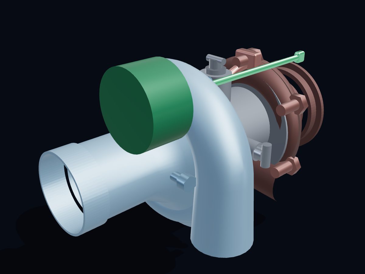 Turbocharger
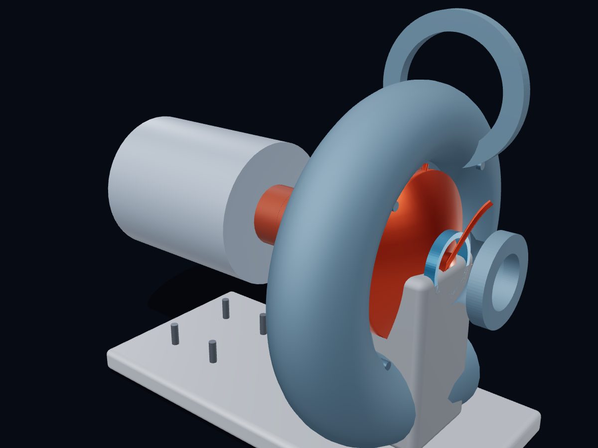 Centrifugal Pump
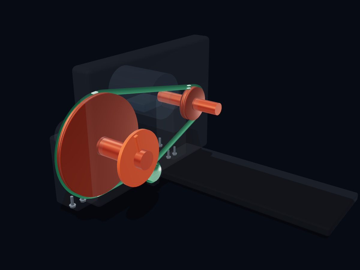 V-Belt Pulley Drive
 Helical Gear Reducer
 Marine Diesel Engine
 Plate Heat Exchanger
 Reciprocating Air Compressor
 Planetary Gearbox