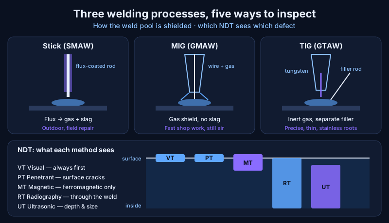
Stick, MIG and TIG welding all melt metal with an electric arc, but each protects the molten weld from the air in a different way — a flux coating, a shielding gas, or an inert gas with a separate filler rod — and that decides where each works best.
After welding, non-destructive testing (NDT) checks the weld for defects without damaging it: some methods look at the surface, others see inside the metal.
In fabrication and repair, the two go together. Choosing the process sets how likely defects are; inspection proves the weld is fit for service before the system is pressure-tested and put to work.
Why does a weld need shielding?
A weld needs shielding because molten steel reacts with oxygen and nitrogen in the air. Without protection, the weld pool absorbs gas and forms pores (porosity), oxides and brittle nitrides.
Every arc welding process therefore wraps the pool in something that keeps air out: a flux that melts into a protective gas and slag, a shielding gas blown from the torch, or both. How that shielding is delivered is the main difference between the processes.
How does stick welding (SMAW) work?
Stick welding — shielded metal arc welding (SMAW) — uses a consumable rod coated in flux. The arc melts the rod, which becomes filler metal, while the coating burns to produce a shielding gas and a layer of slag over the hot weld.
Tulsa Welding School describes it as rugged, suited to outdoor work, and more forgiving of painted or rusty surfaces — which is why it is the classic process for field repair.
The drawbacks are slag that must be chipped off after every pass, and poor results on thin metal (TWS gives under about 1/8 inch, ≈3 mm, as difficult). Slag left between passes is a common defect source.
How does MIG welding (GMAW) work?
MIG welding — gas metal arc welding (GMAW) — feeds a continuous wire electrode through the torch while a shielding gas flows around it. TWS calls it fast, relatively easy to learn once the wire feeder is set up, usable in any position and clean, with no slag. That makes it the workhorse of production fabrication.
Its weakness is the gas: wind blows the shield away, so MIG needs still air and clean surfaces. TWS notes that flux-cored wire (FCAW) solves this outdoors — the flux inside a tubular wire produces its own shielding — at the cost of slag again.
How does TIG welding (GTAW) work?
TIG welding — gas tungsten arc welding (GTAW) — uses a non-consumable tungsten electrode to make the arc, inert shielding gas to protect it, and a filler rod fed separately by hand.
Because heat input and filler are controlled independently, TWS describes TIG as producing very high-quality, precise welds on a wide range of metals, including thin aluminium — but it is slower and takes longer to master.
TIG is the usual choice for stainless steel and for the root pass of critical pipe joints, where a clean, fully penetrated first pass matters most.
| Process | Shielding | Speed | Skill | Best for |
|---|---|---|---|---|
| Stick (SMAW) | Flux coating → gas + slag | Medium | Medium | Outdoor, field repair, rusty or painted steel |
| MIG (GMAW) | Shielding gas | Fast | Easier | Shop production, any position |
| Flux-cored (FCAW) | Flux in wire (± gas) | Fast | Medium | Outdoor alternative to MIG |
| TIG (GTAW) | Inert gas, separate filler | Slow | Hardest | Thin metal, stainless, critical roots |
What are the common weld defects?
The common weld defects are flaws that weaken the joint or start cracks. Accendo Reliability lists the ones inspection looks for:
- Slag inclusions — non-metallic slag trapped inside the weld.
- Undercut — a groove melted into the base metal at the weld edge, leaving it thinner than the parent plate.
- Inadequate penetration — the weld does not reach through the joint thickness.
- Poor fusion — weld metal not properly bonded to the base metal.
- Cracks — Accendo notes metallurgical causes such as incompatible metals or cooling too fast.
- Porosity — gas pores from lost shielding, damp electrodes or dirty surfaces.
How are welds inspected with NDT?
Welds are inspected with several NDT methods, each suited to defects at a different depth. Accendo describes them:
- Visual testing (VT) — always first. A trained inspector checks profile, undercut, surface cracks and spatter, and can spot inadequate penetration and poor fusion at the surface.
- Liquid penetrant testing (PT) — a coloured or fluorescent liquid soaks into surface-breaking cracks by capillary action, and a developer draws it back out to show them. Finds surface defects only, and the surface must be clean; Accendo warns that shot blasting can close over defects.
- Magnetic particle testing (MT) — the part is magnetised and fine iron particles gather where a defect distorts the field. Finds surface and just-below-surface defects, but works only on ferromagnetic metals such as carbon steel. Project Materials notes that 304 and 316 stainless are non-magnetic when annealed, so they are checked with PT instead.
- Radiographic testing (RT) — X-rays or gamma rays pass through the weld onto film or a detector; voids and inclusions let more radiation through and show darker. Sees inside almost any material, but is costly, needs radiation safety, and the image is a shadow that depends on thickness and setup.
- Ultrasonic testing (UT) — a probe sends high-frequency sound into the weld and times echoes from defects, showing their size and depth. Finds internal defects; Accendo notes a dead zone just under the probe and a smallest detectable defect of about half the wavelength — around 1.5 mm in steel at 2 MHz. UT is also the method behind thickness gauging on ship hulls.
| Method | Finds | Works on | Main limit |
|---|---|---|---|
| VT | Surface shape and defects | All | Depends on inspector |
| PT | Surface-breaking cracks | Non-porous metals | Surface only; must be clean |
| MT | Surface + near-surface | Ferromagnetic only | Not for austenitic stainless |
| RT | Internal voids, inclusions | Almost all | Cost, radiation safety |
| UT | Internal defects, depth | Most metals | Dead zone near surface; skill |
The engineering takeaway
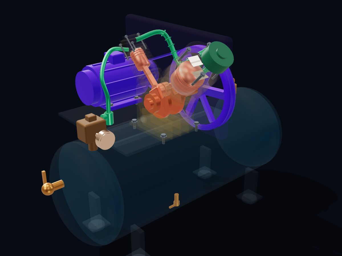
Weld quality is built in by choosing the right process — stick for rugged field work, MIG for fast shop work, TIG for precise and critical joints — and proved by layering inspections: eyes first, then PT or MT for the surface, then RT or UT for what is hidden inside. Accendo's reminder applies to all of them: every NDT method is only as good as the inspector using it. Choose the base material and filler correctly, and the weld has a fair chance before the first arc is struck. To see welded and cast parts side by side in one machine, explore the reciprocating air compressor in 3D, whose air tank is a welded pressure vessel.
 Turbocharger
 Centrifugal Pump
 V-Belt Pulley Drive
 Helical Gear Reducer
 Marine Diesel Engine
 Plate Heat Exchanger
 Reciprocating Air Compressor
 Planetary Gearbox