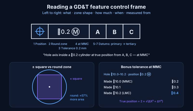
GD&T (geometric dimensioning and tolerancing) is a symbol language on engineering drawings that states how much a part's form, orientation, location and runout may vary while the part still works. Each feature gets a tolerance zone tied to datums, the surfaces the part is measured from.
Instead of a grid of ± dimensions, this gives the designer, machinist and inspector one requirement that they all read the same way.
Anyone who has drafted in AutoCAD or SolidWorks knows the problem GD&T solves: a hole dimensioned "50 ± 0.1 from the edge" says nothing about which edge is the reference, how square the edges are, or whether the hole may tilt. Two shops can make the "same" part differently, and both can pass inspection while the parts still do not fit.
What is GD&T and which standards define it?
GD&T is defined in the US by ASME Y14.5-2018 (reaffirmed in 2024) and internationally by ISO 1101:2017, part of the ISO GPS (geometrical product specification) family. Wevolver traces the idea back to Stanley Parker at the Royal Torpedo Factory, who published it in 1940 after noticing that round tolerance zones accepted working parts that square ones rejected.
The two standards use the same symbols for most things but differ in some rules, so a drawing should always state which one it follows.
What are the GD&T symbols?
ASME Y14.5-2018 has 12 geometric characteristics in five groups. Wevolver notes that older references and ISO 1101 list 14, because ASME withdrew concentricity and symmetry.
| Group | Characteristics | Needs a datum? |
|---|---|---|
| Form | Straightness, flatness, circularity, cylindricity | No |
| Profile | Profile of a line, profile of a surface | Sometimes |
| Orientation | Angularity, perpendicularity, parallelism | Yes |
| Location | Position | Yes |
| Runout | Circular runout, total runout | Yes |
Form controls only the feature's own shape — a flat face being flat — so it needs no datum. Everything that describes a relationship between features (tilted, square, centred, wobbling on rotation) needs a datum to relate to.
How do you read a feature control frame?
A feature control frame is read from left to right, like a sentence. Wevolver lists the compartments:
- Geometric characteristic symbol — for example ⌖ for position.
- Diameter symbol (⌀) — present when the tolerance zone is a cylinder rather than two parallel planes.
- Tolerance value — the total size of the zone, e.g. 0.2 mm.
- Material condition modifier (optional) — Ⓜ for maximum material condition (MMC) or Ⓛ for least material condition (LMC).
- Primary datum (A).
- Secondary datum (B).
- Tertiary datum (C).
So ⌖ | ⌀0.2 Ⓜ | A | B | C reads: "The axis of this hole must lie inside a cylinder 0.2 mm in diameter, at its true position measured from datums A, B and C, when the hole is at its maximum material condition."
What are datums, and why does their order matter?
Datums are the theoretically exact planes, axes or points that every measurement starts from. A datum feature is the real surface on the part (marked with a datum triangle and a letter); the inspection setup simulates a perfect version of it.
Wevolver explains that datums are applied in order, each removing more of the part's six degrees of freedom until it is fully located:
- Primary datum (A) — usually a large, stable face the part sits on. It stops the part moving into it and tilting about two axes.
- Secondary datum (B) — usually an edge or a hole perpendicular to A. It stops further movement and rotation.
- Tertiary datum (C) — locks the last remaining freedom.
The order should follow how the part is actually assembled. If a pump bracket bolts flat onto a base and is then pushed against a shoulder, the base face should be A and the shoulder B — because that is how the bracket will really be held.
What do MMC, LMC and bonus tolerance mean?
MMC, LMC and RFS describe at what size the geometric tolerance applies:
- MMC (maximum material condition) — the size with the most material: the smallest hole or the largest shaft.
- LMC (least material condition) — the largest hole or the smallest shaft.
- RFS (regardless of feature size) — the default; the tolerance is the same whatever the actual size.
When a feature is called out at MMC and is made away from MMC, it gets bonus tolerance. Worked example: a hole is specified as ⌀10.0–10.2 mm with position ⌀0.2 Ⓜ. Made at 10.0 mm (MMC), the position tolerance is 0.2 mm. Made at 10.2 mm, it is 0.2 + 0.2 = 0.4 mm, because the larger hole can still accept the mating pin even if it is a little further out of position. Bonus tolerance passes parts that will genuinely assemble, which keeps scrap down.
Why is a position tolerance zone round?
A position tolerance zone is round because a pin fits a hole equally well whichever direction the hole is off. With ± coordinate tolerances, the zone is a square, and its corners allow more error diagonally than straight across.
Wevolver's example: ±0.13 mm in X and Y gives a 0.26 mm square; the round zone that just contains that square has about 57% more usable area, while still guaranteeing the same fit.
Inspectors check it with the true position formula: position = 2 × √(ΔX² + ΔY²), where ΔX and ΔY are the measured offsets from the exact location. A hole measured 0.06 mm off in X and 0.08 mm off in Y gives 2 × 0.10 = 0.20 mm — exactly on the limit for a ⌀0.2 position tolerance.
The engineering takeaway
GD&T replaces "close enough" with a precise contract: which surfaces the part is measured from, what shape of zone each feature must sit in, and how much extra room the part earns when it is made loose. Read the feature control frame left to right, check the datums against how the part really assembles, and remember that a good tolerance is the loosest one that still guarantees function. The same thinking — define the limit that matters, then check against it — runs through bearing fits and gear alignment. To see why tolerances on shafts, bores and bearing seats matter, explore a helical gear reducer in 3D, where every shaft, gear and bearing has to line up; and for the drawing tools themselves, read AutoCAD vs SolidWorks.
 Turbocharger
 Centrifugal Pump
 V-Belt Pulley Drive
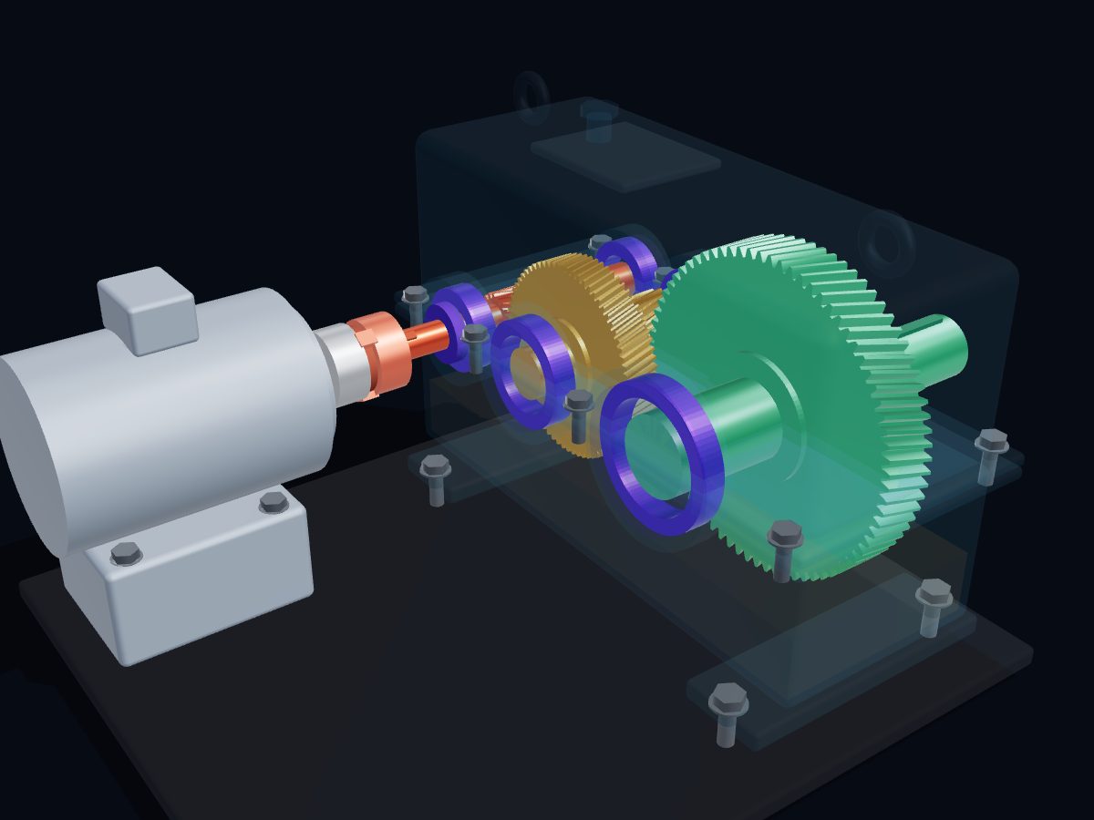 Helical Gear Reducer
 Marine Diesel Engine
 Plate Heat Exchanger
 Reciprocating Air Compressor
 Planetary Gearbox