Engine‑X machine guide
How does an induction motor work?
By Parth Parmar, mechanical design engineer · Updated
An induction motor turns electricity into rotation with no wires to the rotor. Three-phase current in the stator coils makes a magnetic field that rotates round the bore. The field induces current in the bars of the squirrel-cage rotor, and that current in the field pushes the rotor round, always slightly slower than the field.
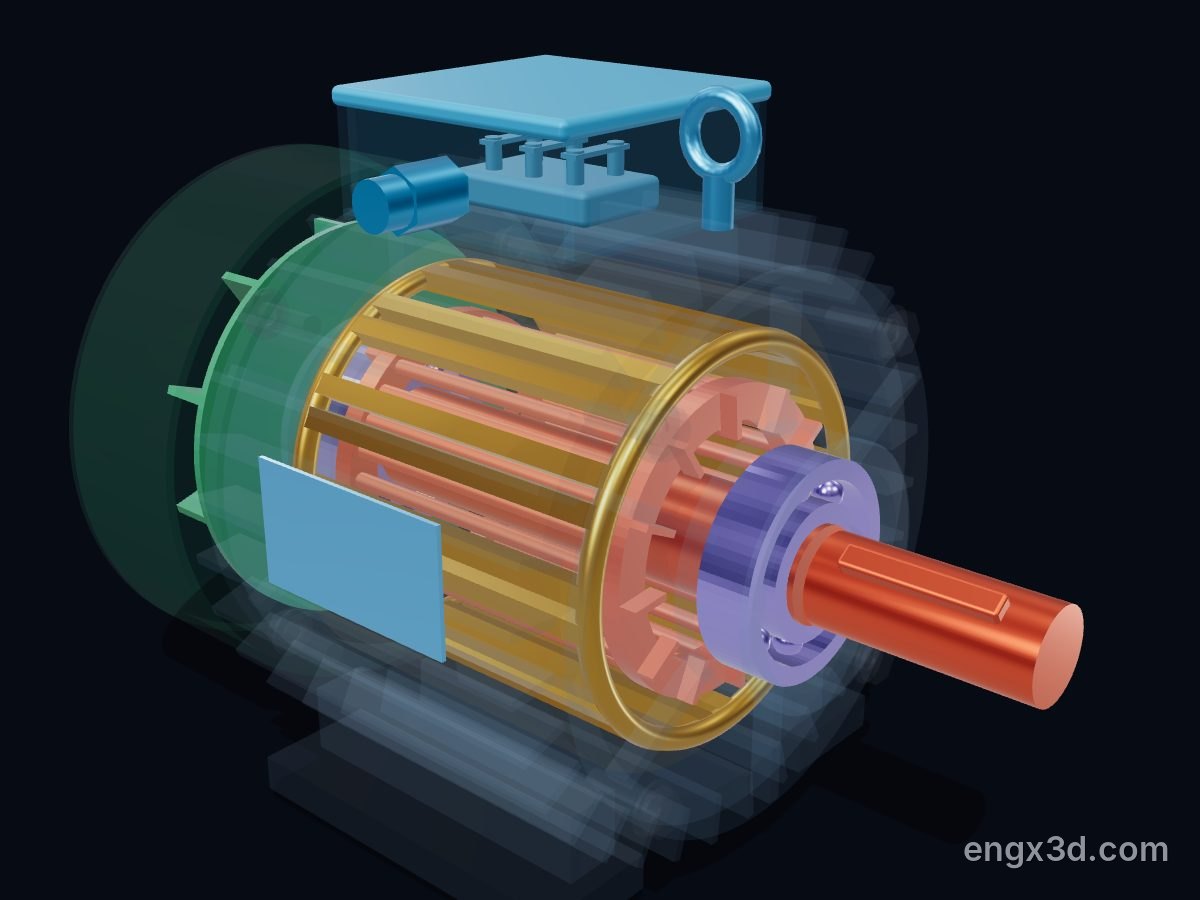
See it work: watch the rotor follow the field as the current peak moves from phase U to V to W, turn on X-ray to see the coils and the squirrel cage, then explode and cut open the motor in 3D, free in your browser.
Open the 3D induction motor →Or download the free 3D model (GLB, STL, AR).
Key facts
| Type in the 3D model | Three-phase squirrel-cage induction motor, TEFC, IEC frame 132M, foot mounted |
|---|---|
| Rating | 7.5 kW, 4 poles, 400 V 50 Hz, 14.3 A (SEVA MX3-132M1-4 class) |
| Synchronous speed | 120 × 50 Hz ÷ 4 poles = 1,500 rpm |
| Rated speed and slip | 1,450 rpm, so the rotor slips 3.3 % behind the field |
| Torque | 49.4 N·m at full load; starting torque 2.2 × and pull-out torque 2.3 × rated |
| Efficiency and power factor | 90.4 % at full load, cos φ 0.84 |
| Starting current | 6.5 × rated current when started direct on line |
| Bearings | 6308 deep-groove ball bearing at each end |
| Shaft and enclosure | Ø38 × 80 mm shaft with a 10 mm key; IP55; insulation class F; 56 kg |
How it works, step by step
- The three-phase supply feeds the stator windings of phases U, V and W, which sit 120 electrical degrees apart round the stator.
- The three currents peak one after another, so the magnetic field they make turns round the bore. With 4 poles on 50 Hz it turns at 1,500 rpm, the synchronous speed.
- The moving field sweeps across the aluminium bars of the rotor cage and induces a voltage in them. The end rings short-circuit the bars, so a large current flows.
- Current in a magnetic field feels a force, so the bars are pushed along with the field and the rotor turns.
- The rotor can never catch the field: at the same speed nothing would be induced and there would be no torque. It settles a little slower, at 1,450 rpm here; the more load, the more slip.
- The shaft passes the torque to the pump, fan or gearbox, and the fan on the back of the shaft blows cooling air over the finned frame.
Main parts of an induction motor
- Stator core and windings — laminated steel with copper coils in three phases; they make the rotating field.
- Rotor core and squirrel cage — laminated core with aluminium bars joined by end rings; current is induced in the bars.
- Shaft and key — carry the rotor and pass the torque to the driven machine.
- Bearings — two ball bearings in the end shields hold the rotor centred in the air gap.
- End shields — close the frame and locate the bearings on the centre line.
- Frame — the finned, foot-mounted housing that holds the stator and sheds the heat.
- Cooling fan and fan cover — blow air along the fins; the cover guides the air and guards the fan.
- Terminal box and terminal block — where the supply cable connects and the windings are linked in star or delta.
How do you calculate the speed of an induction motor?
Synchronous speed is 120 × frequency ÷ number of poles. On 50 Hz a 4-pole motor gives 120 × 50 ÷ 4 = 1,500 rpm. The rotor runs a few percent slower: actual speed = synchronous speed × (1 − slip). With 3.3 % slip this motor runs at 1,450 rpm.
| Poles | Synchronous speed at 50 Hz | at 60 Hz |
|---|---|---|
| 2 | 3,000 rpm | 3,600 rpm |
| 4 | 1,500 rpm | 1,800 rpm |
| 6 | 1,000 rpm | 1,200 rpm |
| 8 | 750 rpm | 900 rpm |
Slip is typically 2 to 5 % at full load, so a real motor runs just below these speeds.
Why does an induction motor need slip?
Because the rotor current is induced only when the field moves past the bars. If the rotor turned exactly with the field there would be no relative motion, no induced current and no torque. Load and friction slow it, the field cuts the bars again, and the rotor settles where its torque matches the load.
What are the most common causes of induction motor failure?
Bearings fail most often. Large surveys put bearings at about 41 to 44 % of motor failures, stator windings at 26 to 36 % and the rotor at 8 to 9 %. Bearing noise, vibration and heat are the first things to check on a motor that sounds wrong.
- Bearings: wrong greasing, misalignment, too much belt tension and stray currents from inverter drives all shorten their life.
- Windings: heat is the enemy of the insulation, so overload, blocked fins or a damaged fan show up as winding failures later.
- Rotor: cracked or broken cage bars are rarer, and show as a drop in torque and a beat in the motor noise.
Common questions
What is the difference between a squirrel-cage and a slip-ring motor?
A squirrel-cage rotor has bars shorted by end rings and no electrical connection. A slip-ring (wound-rotor) motor has insulated rotor windings brought out to slip rings, so resistance can be added to change starting torque and speed.
Why is it called an induction motor?
Because the rotor current is induced by the stator’s rotating field, the same way a transformer induces current in its secondary winding, rather than being fed in through brushes.
Why does an induction motor take a high current when it starts?
At standstill the field sweeps the rotor bars at full synchronous speed, inducing a very large rotor current. This motor takes about 6.5 times its rated current when started direct on line.
What does TEFC mean?
Totally enclosed, fan cooled. The inside of the motor is sealed from outside air, and a fan on the shaft blows air over the finned frame to remove the heat.
What is the difference between star and delta connection?
They are two ways of linking the three windings on the terminal block. A motor rated 400/690 V runs in delta on a 400 V supply and in star on 690 V; star-delta starting uses star briefly to cut the starting current.
Sources
References for the facts on this page, and further reading:
- SEVA — MX3-132M1-4 data sheet (7.5 kW, 4-pole, 1,450 rpm, 14.26 A, 49.4 N·m, 90.4 %, cos φ 0.84, 6308 bearings)
- Control Engineering — Anatomy of an AC induction motor (synchronous speed 120 f / p, 2–5 % slip, TEFC)
- Electrical Easy — Working principle and types of induction motors (rotating field, slip, squirrel cage vs slip ring)
- Reliability Magazine — Electric motor failure statistics (EPRI and IEEE surveys)
- FRAMO — FRA1 IE3 132M4 7.5 kW 400/690 V 50 Hz B3 data sheet
Related reading on the blog
Ball, roller or journal bearing? How bearing types work and how to choose · Why V-belts slip, squeal and fail
More machine guides
Compare: Belt vs chain vs gear drive: which is better?
How does a turbocharger work? · How does a centrifugal pump work? · How does a V-belt pulley drive work? · How does a gear reducer work? · Turbocharger vs supercharger: what's the difference? · Centrifugal vs positive displacement pump: what's the difference? · How does a marine diesel engine work? · How does a plate heat exchanger work? · How does a reciprocating air compressor work? · How does a planetary gearbox work? · How does a turbofan jet engine work? · How does a gate valve work? · How does a car differential work? · How does a manual gearbox work? · How does a butterfly valve work? · How does a car engine work?
Need an interactive 3D page like this for your own machine? See Work with Engine‑X.