By Parth Parmar, mechanical design engineer · 39 pieces, 21 parts · Updated
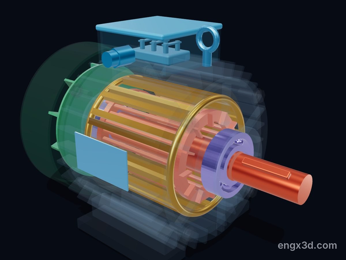
An induction motor turns electricity into rotation with no wires to the rotor. Three-phase current in the stator coils makes a magnetic field that rotates round the bore. The field induces current in the bars of the squirrel-cage rotor, and that current in the field pushes the rotor round, always slightly slower than the field.
Single parts: scroll to the parts list. These are learning models, not a print kit: some parts touch or overlap and there are no fit tolerances.
Free for personal and educational use under CC BY-NC 4.0. Credit “Engine-X by Parth Parmar (engx3d.com)” when you share or remix it. Don’t sell the files or prints. For commercial use, get in touch. Every file carries the Engine-X mark and a hidden digital fingerprint that identifies it.
Every part with a picture, what it does and its own STL file: motor shaft, shaft key, rotor core, squirrel cage (rotor bars and end rings), stator core, stator coil, de bearing (6308), nde bearing (6308) and more. Open any part in the live 3D atlas to see where it sits and how it moves. A part used several times (valves, bolts) is shown once with its count.
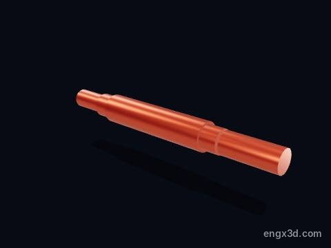
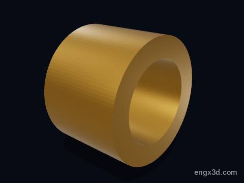
The motor shaft carries the rotor and passes the torque to the driven machine through its 38 mm drive-end extension. At full load it delivers about 49.4 N·m at 1450 rpm.
More about this part
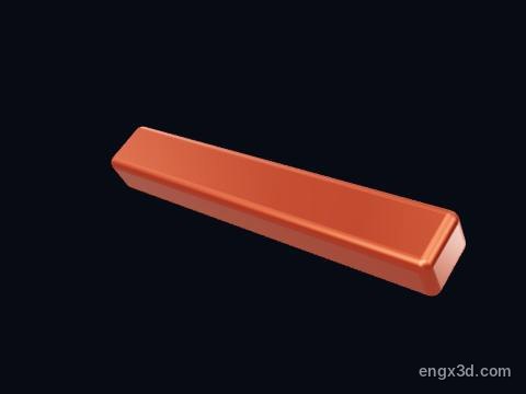
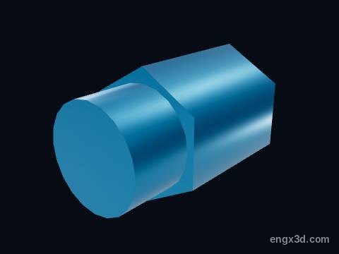
The key in the drive-end keyway locks the coupling or pulley to the shaft.
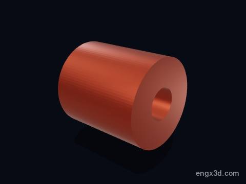
The rotor core is the laminated steel cylinder on the shaft that carries the squirrel cage. It turns 3.3 % slower than the rotating field (1450 rpm against 1500 rpm); that slip is what lets the field keep inducing current in the rotor bars.
More about this part
The air gap between rotor and stator is only a fraction of a millimetre in a motor this size, which is why worn bearings that let the rotor drop can make it rub the stator.
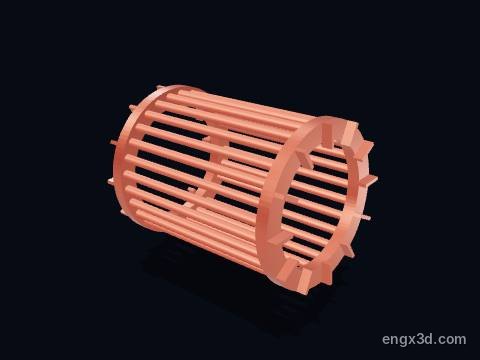
The squirrel cage is the rotor winding: 28 aluminium bars cast into the rotor slots and joined at both ends by short-circuiting end rings. The rotating field induces current in the bars, and that current in the field makes the torque.
More about this part
It has no brushes or electrical connection at all, which is why squirrel-cage motors are so simple and reliable.
Bars are usually skewed slightly along the rotor to make the torque smoother and quieter; this model draws them straight.
The stator core is a stack of thin, insulated electrical-steel laminations pressed into the frame. It carries the magnetic field; the 36 slots around its bore hold the copper windings.
More about this part
Laminations, not solid steel, because a solid core would carry large eddy currents and heat up.
Drawn see-through so the windings inside stay visible.
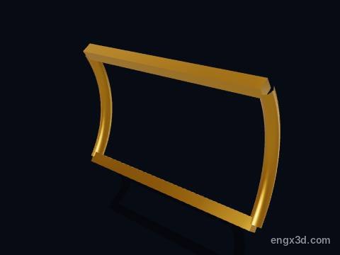
A stator coil is one group of insulated copper turns laid in the stator slots. Three-phase current in the coils of phases U, V and W, set 120 electrical degrees apart, makes a magnetic field that rotates round the bore.
More about this part
With 4 poles on 50 Hz the field turns at 120 × 50 / 4 = 1500 rpm, the synchronous speed.
Winding insulation is class F here, rated to 155 °C.
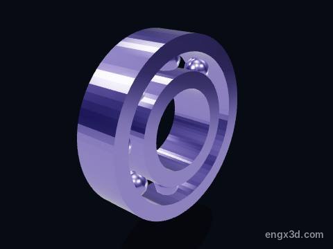
A motor bearing supports the rotor shaft in an end shield. This motor has one deep-groove ball bearing at each end (6308), which carries the rotor weight, the belt or coupling load and some axial load.
More about this part
Bearings are the most common cause of motor failure: about 41 % of failures in an EPRI survey and 44 % in an IEEE survey of large motors.
Over-greasing, misalignment, too much belt tension and currents from inverter drives all shorten bearing life.
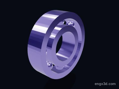
A motor bearing supports the rotor shaft in an end shield. This motor has one deep-groove ball bearing at each end (6308), which carries the rotor weight, the belt or coupling load and some axial load.
More about this part
Bearings are the most common cause of motor failure: about 41 % of failures in an EPRI survey and 44 % in an IEEE survey of large motors.
Over-greasing, misalignment, too much belt tension and currents from inverter drives all shorten bearing life.
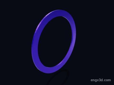
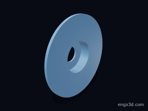
The bearing preload washer is a thin wave spring behind the non-drive-end bearing. It pushes the bearing lightly sideways so the balls always run under a little load, which keeps them quiet and lets the shaft grow with heat.
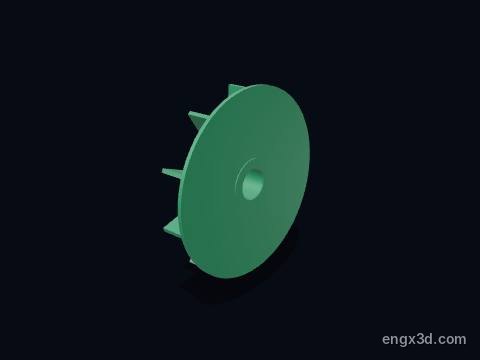
The cooling fan sits on the non-drive end of the shaft and turns with it. It blows air along the outside fins of the frame, carrying away the heat lost in the windings and the core.
More about this part
Because the fan turns with the shaft, a motor run slowly from an inverter gets less cooling; at low speed and full torque it may need a separate fan.
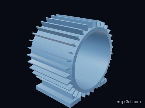
The motor frame (housing) is the finned cast casing that holds the stator and carries the motor on its feet. This IEC frame 132 puts the shaft centre 132 mm above the feet; the cooling fins along its outside carry the heat that the fan's air blows away.
More about this part
TEFC means totally enclosed, fan cooled: no outside air passes through the windings, which keeps dust and water out (IP55 here).
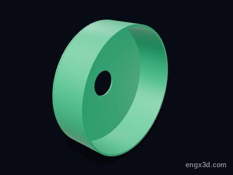
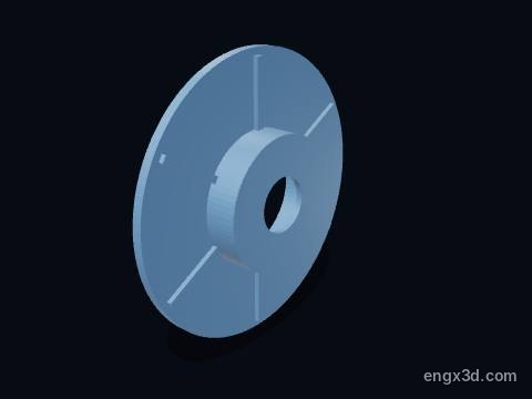
An end shield (end bell, bearing bracket) closes one end of the motor frame and holds a bearing exactly on the centre line of the stator bore. Its spigot fit keeps the rotor centred in the small air gap.
An end shield (end bell, bearing bracket) closes one end of the motor frame and holds a bearing exactly on the centre line of the stator bore. Its spigot fit keeps the rotor centred in the small air gap.
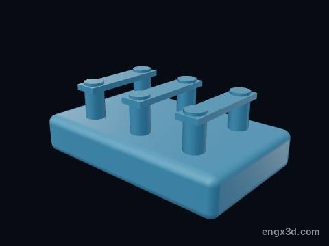
The terminal block carries the six winding ends U1, V1, W1, U2, V2, W2. Brass links across it connect the windings in star or in delta, so the same motor can run on 400 V (delta) or 690 V (star).
More about this part
At 400 V this motor draws about 14.26 A at full load.
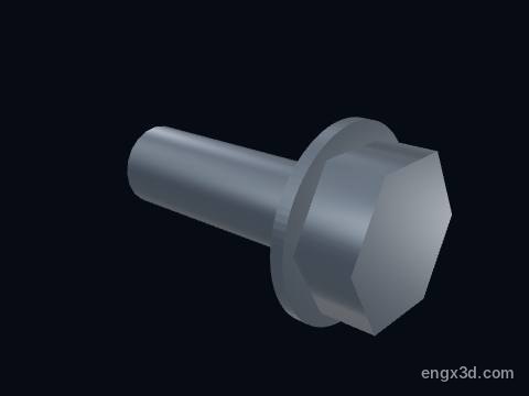
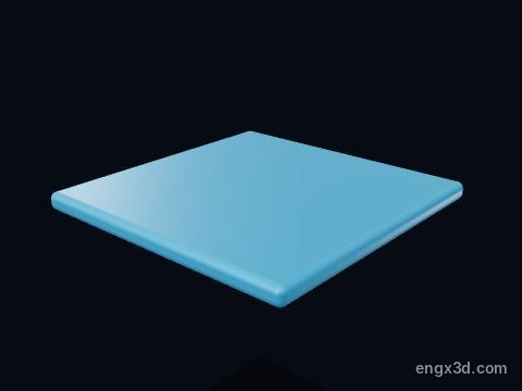
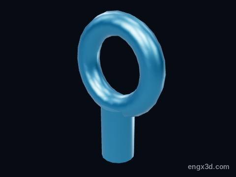
The lifting eye bolt on top of the frame is for lifting the motor alone. This 7.5 kW motor weighs about 56 kg; the eye is not meant for lifting the motor together with the machine it drives.
The nameplate (rating plate) gives the motor's data: 7.5 kW, 1450 rpm, 14.26 A at 400 V, 90.4 % efficiency, power factor 0.84, frame size and bearing types. It is the first thing to read before connecting or replacing a motor.
Yes. The induction motor 3D model is free for personal and educational use under CC BY-NC 4.0: credit "Engine-X by Parth Parmar (engx3d.com)". Selling the files or prints, or other commercial use, needs written permission.
Which file formats is the induction motor 3D model in?
GLB (glTF 2.0) with colours and named parts, STL in millimetres (Z-up) for CAD, slicers and 3D printing, USDZ for AR on iPhone, and a ZIP with all 21 parts as separate STL files.
How many parts does the induction motor 3D model have?
39 named pieces in 6 systems (rotor & shaft, stator & windings, bearings, cooling fan & cover, frame & end shields, terminal box & fittings). Repeated pieces such as bolts are folded together, which leaves 21 different parts, each one downloadable on its own.
Can I 3D print the induction motor model?
Yes, download the STL (whole machine or single parts) and open it in your slicer. It is a learning model at real scale, not a print kit: some parts touch or overlap and there are no fit tolerances, so scale it and print parts one by one.
How do I see the induction motor in AR on my phone?
Tap "View in your room" on this page. Android opens Google Scene Viewer and iPhone opens AR Quick Look, both without an app, and you can place the model at real size on the floor or a table.
Can I see the induction motor working in 3D?
Yes. Tap "Play live 3D here" or open the Engine-X atlas (engx3d.com/atlas#m=inductionmotor): it runs in the browser with true motion, and you can explode it, cut it open and X-ray it.
How to credit or cite this model
Credit line: Induction motor 3D model, Engine-X by Parth Parmar (engx3d.com)
Citation: Parmar, P. (2026). Induction motor 3D model [3D model, CC BY-NC 4.0]. Engine-X. https://engx3d.com/3d-models/induction-motor
Used this model?
For a class, a project, a print or a video? Tell us how it went. With your OK, we may feature your work here.
 Open full screen →
 View in your room · AR