By Parth Parmar, mechanical design engineer · 47 pieces, 42 parts · Updated
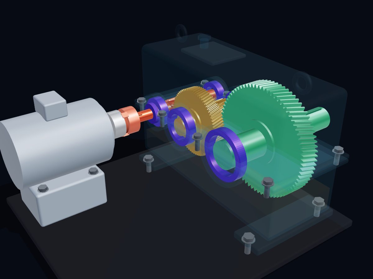
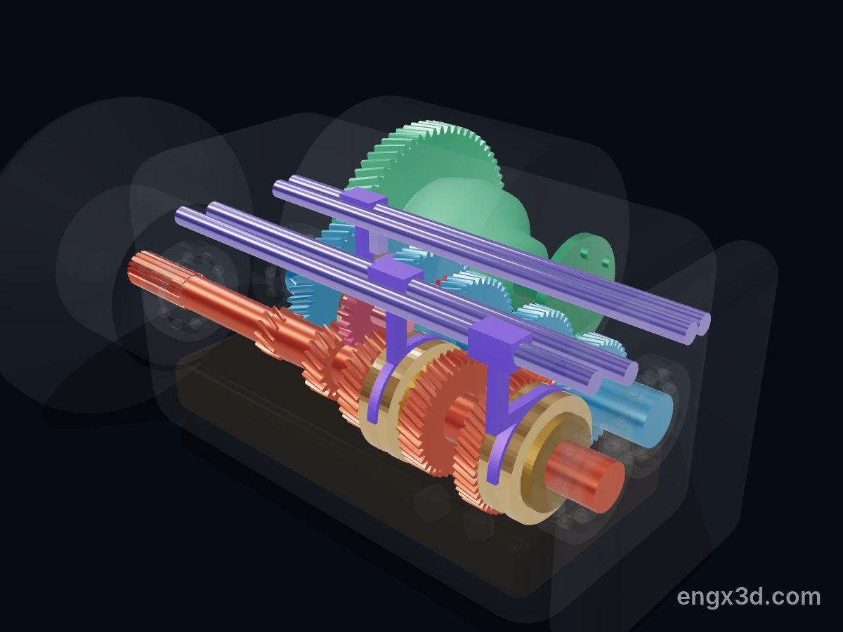
A manual gearbox changes how fast the wheels turn for each turn of the engine. All its gear pairs stay in mesh, but only one is locked to the shaft at a time. Moving the gear lever slides a synchroniser sleeve, which first matches the speeds and then locks the chosen gear to its shaft.
Single parts: scroll to the parts list. These are learning models, not a print kit: some parts touch or overlap and there are no fit tolerances.
Free for personal and educational use under CC BY-NC 4.0. Credit “Engine-X by Parth Parmar (engx3d.com)” when you share or remix it. Don’t sell the files or prints. For commercial use, get in touch. Every file carries the Engine-X mark and a hidden digital fingerprint that identifies it.
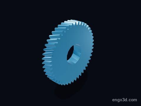
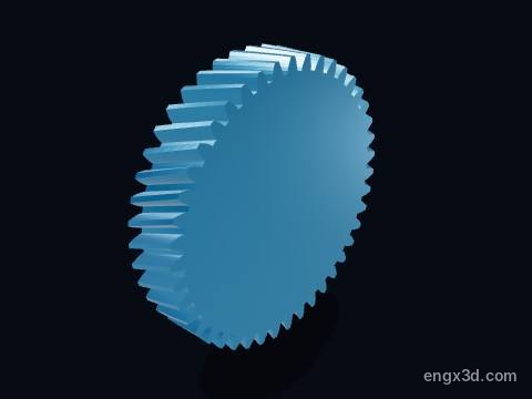
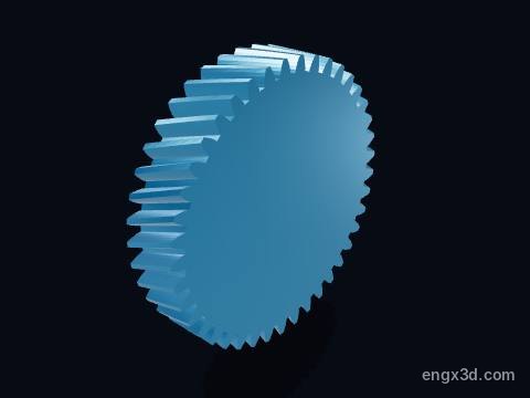
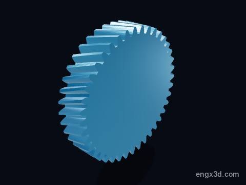
Every part with a picture, what it does and its own STL file: input shaft, 1st gear drive gear (12 teeth), 2nd gear drive gear (20 teeth), 3rd gear drive gear (30 teeth), 4th gear drive gear (38 teeth), 5th gear drive gear (47 teeth), output shaft, 1st gear driven gear (50 teeth) and more. Open any part in the live 3D atlas to see where it sits and how it moves. A part used several times (valves, bolts) is shown once with its count.
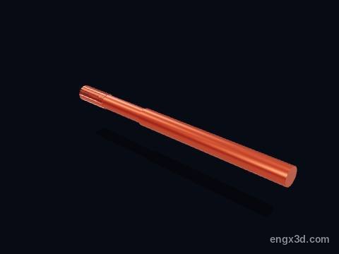
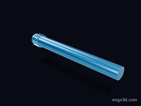
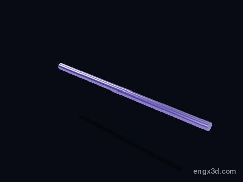
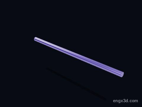
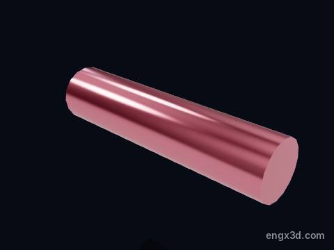
The input shaft takes the engine's turning force from the clutch disc on its splined front end. It carries the five drive gears: 1st and 2nd are fixed to it, while 3rd, 4th and 5th spin freely on it until a synchroniser locks one of them on.
More about this part
It turns at engine speed whenever the clutch is engaged, whichever gear is selected.
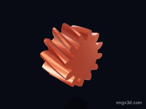
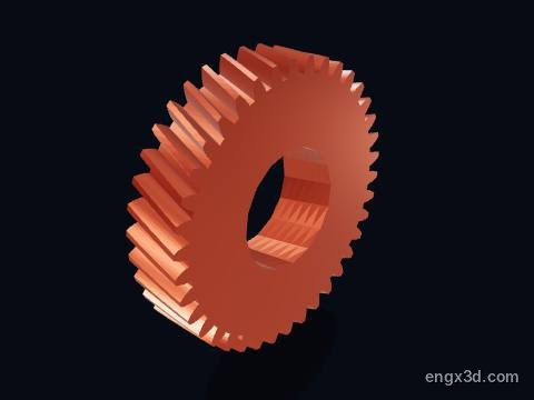
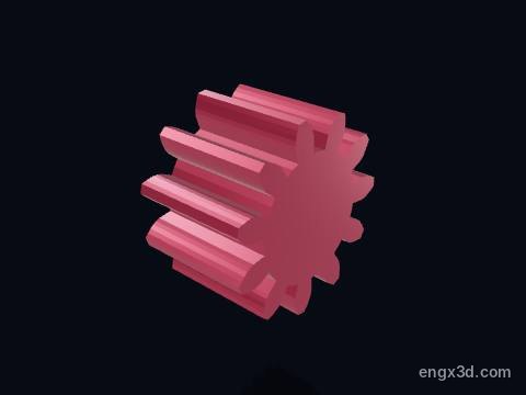
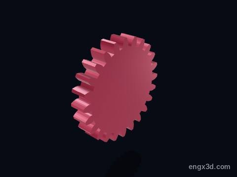
The 1st gear drive gear sits on the input shaft and has 12 helical teeth. It is always in mesh with the 50-tooth driven gear on the output shaft, giving 50 : 12 = 4.167 : 1.
More about this part
It is fixed to the input shaft, so it always turns at engine speed.
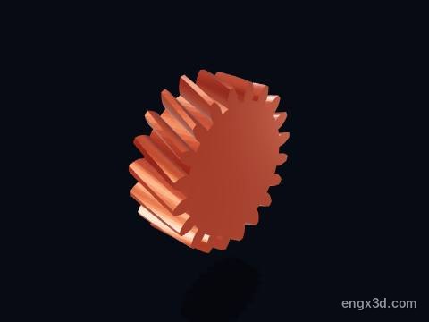
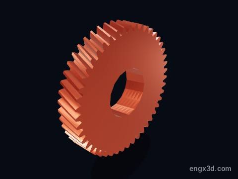
The 2nd gear drive gear sits on the input shaft and has 20 helical teeth. It is always in mesh with the 46-tooth driven gear on the output shaft, giving 46 : 20 = 2.300 : 1.
More about this part
It is fixed to the input shaft, so it always turns at engine speed.
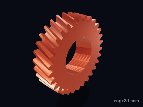
The 3rd gear drive gear sits on the input shaft and has 30 helical teeth. It is always in mesh with the 43-tooth driven gear on the output shaft, giving 43 : 30 = 1.433 : 1.
More about this part
It spins freely on needle bearings until the 3-4 synchroniser locks it to the input shaft.
The 4th gear drive gear sits on the input shaft and has 38 helical teeth. It is always in mesh with the 41-tooth driven gear on the output shaft, giving 41 : 38 = 1.079 : 1.
More about this part
It spins freely on needle bearings until the 3-4 synchroniser locks it to the input shaft.
The 5th gear drive gear sits on the input shaft and has 47 helical teeth. It is always in mesh with the 40-tooth driven gear on the output shaft, giving 40 : 47 = 0.851 : 1.
More about this part
It spins freely on needle bearings until the 5th gear synchroniser locks it to the input shaft.
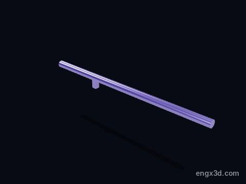
The output shaft carries the five driven gears and the final drive pinion. It turns slower than the input shaft in the lower gears and faster in 5th, and drives the differential through the pinion on its end.
More about this part
In a two-shaft front-wheel-drive gearbox there is no separate layshaft: the output shaft drives the final drive gear directly.
Carries: 5 driven gears, reverse gear, final drive pinion
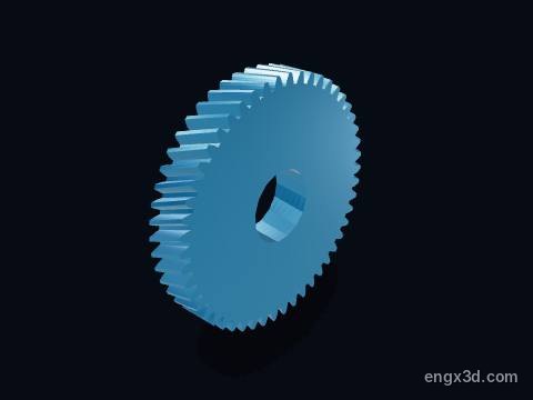
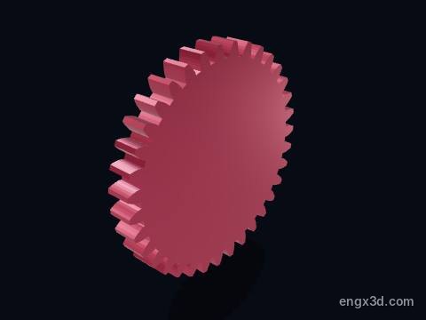
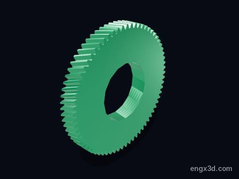
The 1st gear driven gear on the output shaft has 50 helical teeth and meshes with the 12-tooth drive gear on the input shaft: 50 : 12 gives a ratio of 4.167 : 1.
More about this part
It spins freely on needle bearings until the 1-2 synchroniser locks it to the output shaft.
In 1st the output shaft turns 4.167 times slower than the engine and carries 4.167 times the torque, less friction.
The 2nd gear driven gear on the output shaft has 46 helical teeth and meshes with the 20-tooth drive gear on the input shaft: 46 : 20 gives a ratio of 2.300 : 1.
More about this part
It spins freely on needle bearings until the 1-2 synchroniser locks it to the output shaft.
In 2nd the output shaft turns 2.300 times slower than the engine and carries 2.300 times the torque, less friction.
The 3rd gear driven gear on the output shaft has 43 helical teeth and meshes with the 30-tooth drive gear on the input shaft: 43 : 30 gives a ratio of 1.433 : 1.
More about this part
It is fixed to the output shaft.
In 3rd the output shaft turns 1.433 times slower than the engine and carries 1.433 times the torque, less friction.
The 4th gear driven gear on the output shaft has 41 helical teeth and meshes with the 38-tooth drive gear on the input shaft: 41 : 38 gives a ratio of 1.079 : 1.
More about this part
It is fixed to the output shaft.
In 4th the output shaft turns 1.079 times slower than the engine and carries 1.079 times the torque, less friction.
The 5th gear driven gear on the output shaft has 40 helical teeth and meshes with the 47-tooth drive gear on the input shaft: 40 : 47 gives a ratio of 0.851 : 1.
More about this part
It is fixed to the output shaft.
A ratio below 1 is an overdrive: in 5th the output shaft turns faster than the engine, which lowers engine speed on the motorway.
Hubs, sliding sleeves and brass blocker rings for 1-2, 3-4 and 5th.
1-2 synchroniser hub
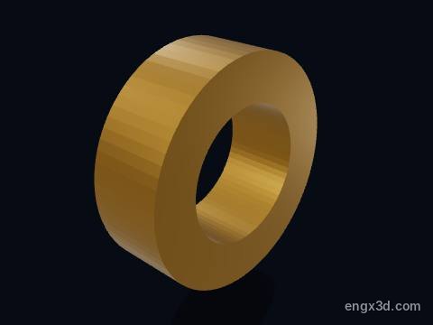
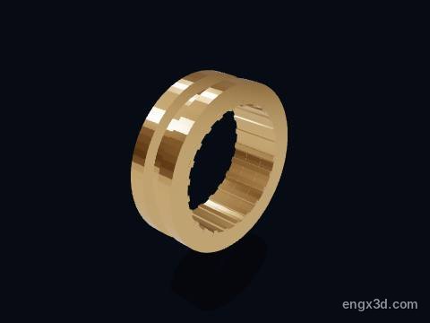
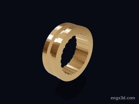
A synchroniser hub is splined solidly to its shaft and carries the sliding sleeve. It is the link that finally passes the drive from the selected gear to the shaft.
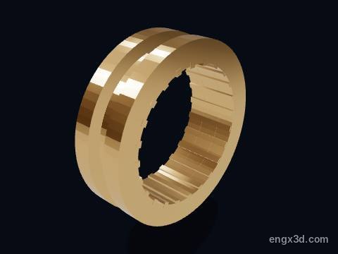
A synchroniser sleeve slides along the hub when the shift fork moves it. Once the blocker ring has matched the speeds, its internal teeth slide over the dog teeth on the gear and lock that gear to the shaft.
More about this part
If the speeds are not yet matched the blocker ring stops the sleeve, which is the resistance felt in the gear lever during a quick shift.
A worn sleeve or worn dog teeth can let the gear pop out of mesh under load.
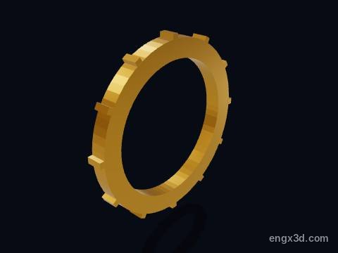
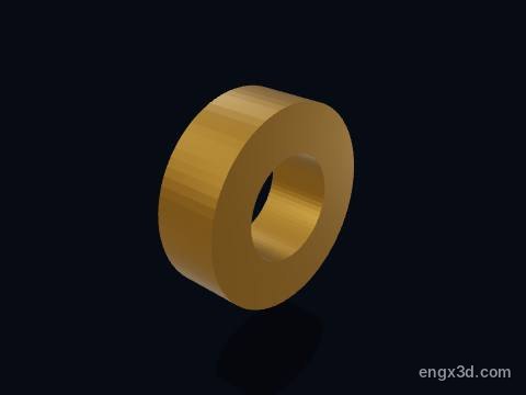
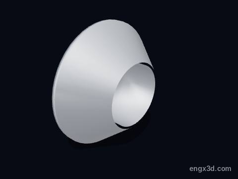
A blocker ring (baulk ring, synchro ring) is a brass cone ring between the sleeve and a gear. When the sleeve pushes it against the gear's cone, friction brings the gear to the shaft's speed before the sleeve can engage, so the gear changes without a crunch.
More about this part
Blocker rings are wear parts. A crunch going into one particular gear usually means its synchro ring is worn; the 2nd gear synchro often wears first.
A synchroniser hub is splined solidly to its shaft and carries the sliding sleeve. It is the link that finally passes the drive from the selected gear to the shaft.
A synchroniser sleeve slides along the hub when the shift fork moves it. Once the blocker ring has matched the speeds, its internal teeth slide over the dog teeth on the gear and lock that gear to the shaft.
More about this part
If the speeds are not yet matched the blocker ring stops the sleeve, which is the resistance felt in the gear lever during a quick shift.
A worn sleeve or worn dog teeth can let the gear pop out of mesh under load.
A synchroniser hub is splined solidly to its shaft and carries the sliding sleeve. It is the link that finally passes the drive from the selected gear to the shaft.
A synchroniser sleeve slides along the hub when the shift fork moves it. Once the blocker ring has matched the speeds, its internal teeth slide over the dog teeth on the gear and lock that gear to the shaft.
More about this part
If the speeds are not yet matched the blocker ring stops the sleeve, which is the resistance felt in the gear lever during a quick shift.
A worn sleeve or worn dog teeth can let the gear pop out of mesh under load.
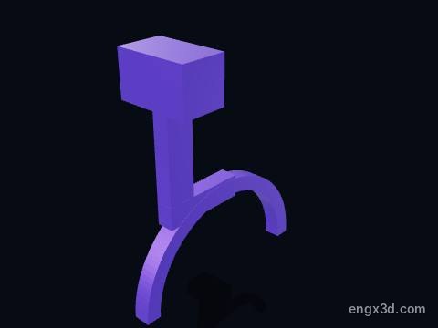
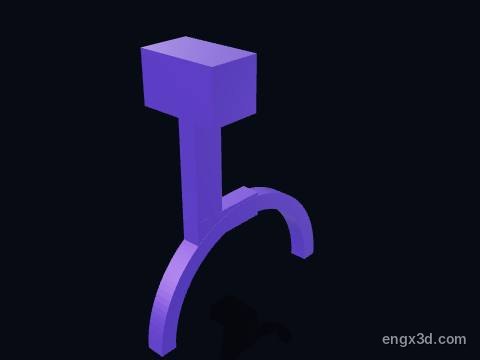
A shift fork rides in the groove of a synchroniser sleeve. The gear lever moves its shift rail, and the fork slides the sleeve towards the chosen gear.
More about this part
A bent or worn fork can stop a gear going fully in, or let it jump out.
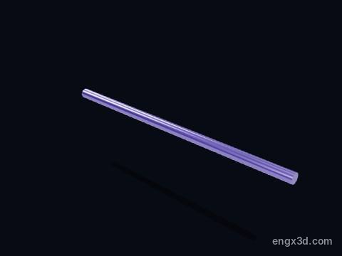
A shift rail is the rod that carries one shift fork. The gear lever picks one rail and slides it; an interlock stops two rails moving at once, so two gears can never be engaged together.
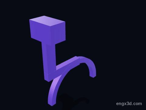
A shift fork rides in the groove of a synchroniser sleeve. The gear lever moves its shift rail, and the fork slides the sleeve towards the chosen gear.
More about this part
A bent or worn fork can stop a gear going fully in, or let it jump out.
A shift rail is the rod that carries one shift fork. The gear lever picks one rail and slides it; an interlock stops two rails moving at once, so two gears can never be engaged together.
A shift fork rides in the groove of a synchroniser sleeve. The gear lever moves its shift rail, and the fork slides the sleeve towards the chosen gear.
More about this part
A bent or worn fork can stop a gear going fully in, or let it jump out.
A shift rail is the rod that carries one shift fork. The gear lever picks one rail and slides it; an interlock stops two rails moving at once, so two gears can never be engaged together.
A shift rail is the rod that carries one shift fork. The gear lever picks one rail and slides it; an interlock stops two rails moving at once, so two gears can never be engaged together.
The reverse driven gear has 35 straight-cut teeth and is fixed to the output shaft. It turns backwards only when the reverse idler is slid into mesh with it.
The reverse idler gear has 24 teeth and sits on its own short shaft. Selecting reverse slides it along its shaft into mesh with the reverse drive gear and the reverse driven gear, and putting a third gear in the chain reverses the direction of the output shaft.
More about this part
Reverse is usually not synchronised and uses straight-cut teeth, so it should only be selected with the car stopped; that is why it can crunch and why it whines when driving backwards.
The final drive gear (crown wheel) has 69 teeth and is bolted to the differential case. With the 14-tooth pinion it reduces the output shaft speed 4.93 times before the drive reaches the wheels.
More about this part
Overall ratio in 1st is 4.167 × 4.929 ≈ 20.5 : 1, so the engine turns about 20 times for one turn of the wheels.
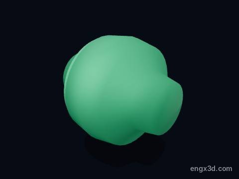
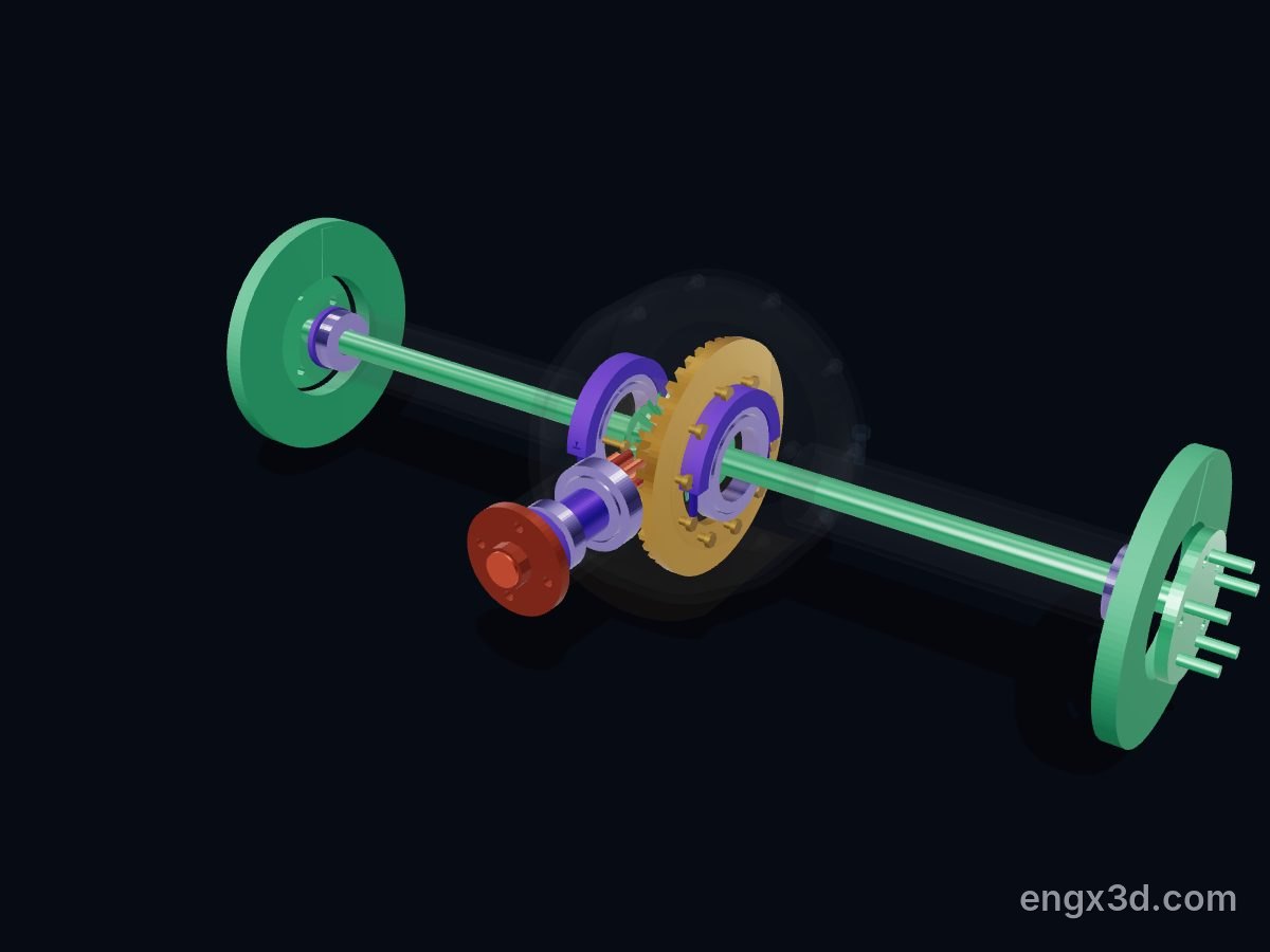
The differential case carries the final drive gear and the differential gears inside it. It splits the drive between the two front wheels and lets them turn at different speeds in corners.
More about this part
See the Engine-X car differential for how the gears inside work.
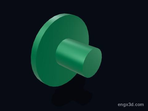
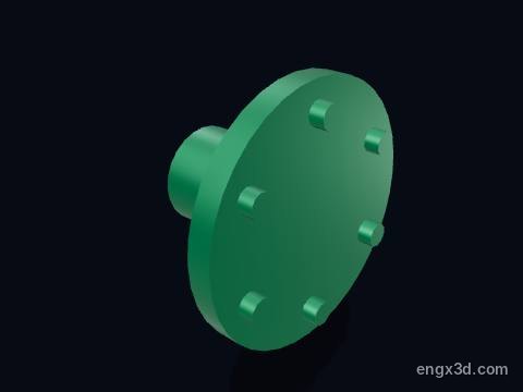
A drive flange is where one of the two drive shafts bolts to the gearbox. It turns with its side of the differential and carries the drive out to the front wheel.
A drive flange is where one of the two drive shafts bolts to the gearbox. It turns with its side of the differential and carries the drive out to the front wheel.
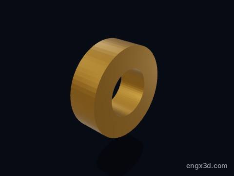
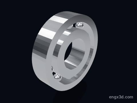
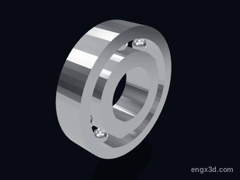
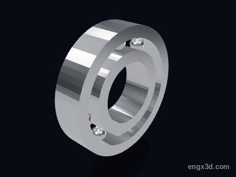
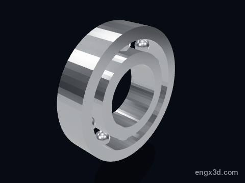
A shaft bearing holds one end of the input or output shaft in the gearbox housing. Ball and roller bearings take the gears' radial load and the axial thrust that the helical teeth create.
More about this part
A growl that changes with road speed in every gear, but not in neutral, often points to a worn shaft bearing.
A shaft bearing holds one end of the input or output shaft in the gearbox housing. Ball and roller bearings take the gears' radial load and the axial thrust that the helical teeth create.
More about this part
A growl that changes with road speed in every gear, but not in neutral, often points to a worn shaft bearing.
A shaft bearing holds one end of the input or output shaft in the gearbox housing. Ball and roller bearings take the gears' radial load and the axial thrust that the helical teeth create.
More about this part
A growl that changes with road speed in every gear, but not in neutral, often points to a worn shaft bearing.
A shaft bearing holds one end of the input or output shaft in the gearbox housing. Ball and roller bearings take the gears' radial load and the axial thrust that the helical teeth create.
More about this part
A growl that changes with road speed in every gear, but not in neutral, often points to a worn shaft bearing.
The gearbox housing holds the shafts in line and contains the gear oil. In this transaxle it also houses the final drive and differential, so the whole unit bolts straight to the side of the engine.
More about this part
Volkswagen made the 02T housing from magnesium, which saved 2.5 kg over aluminium.
The end cover closes the far end of the gearbox housing over the 5th gear set, which sits outside the main bearing wall in many front-wheel-drive gearboxes.
Yes. The manual gearbox 3D model is free for personal and educational use under CC BY-NC 4.0: credit "Engine-X by Parth Parmar (engx3d.com)". Selling the files or prints, or other commercial use, needs written permission.
Which file formats is the manual gearbox 3D model in?
GLB (glTF 2.0) with colours and named parts, STL in millimetres (Z-up) for CAD, slicers and 3D printing, USDZ for AR on iPhone, and a ZIP with all 42 parts as separate STL files.
How many parts does the manual gearbox 3D model have?
47 named pieces in 7 systems (input shaft & drive gears, output shaft & driven gears, synchronisers, shift forks & rails, reverse gears, final drive, housing, bearings & oil). Repeated pieces such as bolts are folded together, which leaves 42 different parts, each one downloadable on its own.
Can I 3D print the manual gearbox model?
Yes, download the STL (whole machine or single parts) and open it in your slicer. It is a learning model at real scale, not a print kit: some parts touch or overlap and there are no fit tolerances, so scale it and print parts one by one.
How do I see the manual gearbox in AR on my phone?
Tap "View in your room" on this page. Android opens Google Scene Viewer and iPhone opens AR Quick Look, both without an app, and you can place the model at real size on the floor or a table.
Can I see the manual gearbox working in 3D?
Yes. Tap "Play live 3D here" or open the Engine-X atlas (engx3d.com/atlas#m=manualgearbox): it runs in the browser with true motion, and you can explode it, cut it open and X-ray it.
How to credit or cite this model
Credit line: Manual gearbox 3D model, Engine-X by Parth Parmar (engx3d.com)
Citation: Parmar, P. (2026). Manual gearbox 3D model [3D model, CC BY-NC 4.0]. Engine-X. https://engx3d.com/3d-models/manual-gearbox
Used this model?
For a class, a project, a print or a video? Tell us how it went. With your OK, we may feature your work here.
 Open full screen →
 View in your room · AR