By Parth Parmar, mechanical design engineer · 38 pieces, 21 parts · Updated
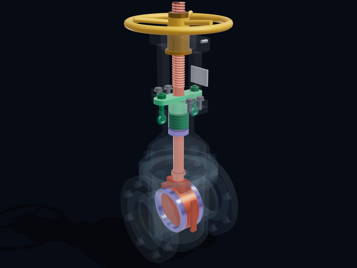
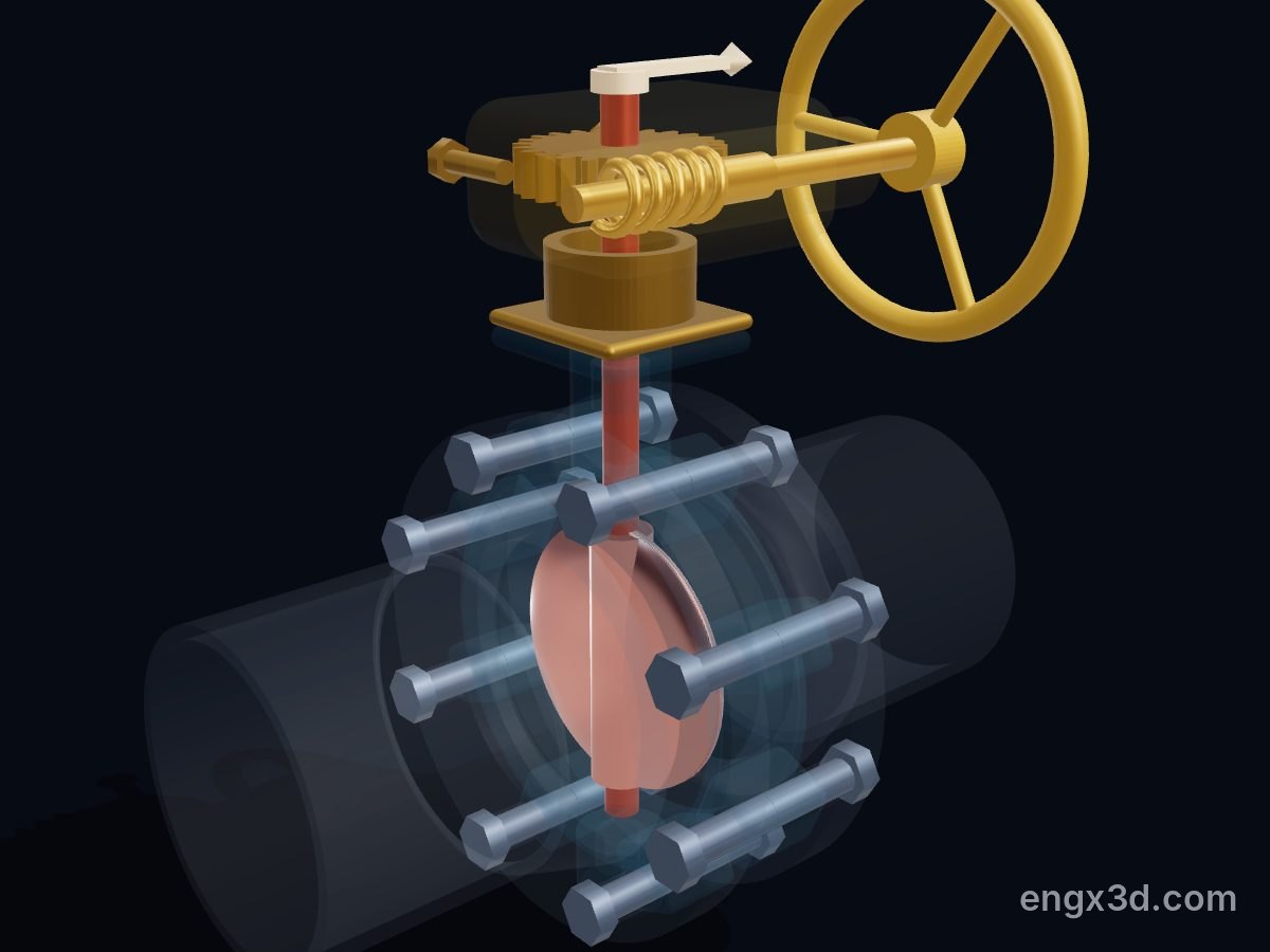
A butterfly valve controls flow with a round disc mounted on a stem across the pipe. Turned square to the flow, the disc presses into a seat and shuts the pipe; a quarter turn puts it edge-on and the valve is fully open. Any angle in between throttles the flow.
Single parts: scroll to the parts list. These are learning models, not a print kit: some parts touch or overlap and there are no fit tolerances.
Free for personal and educational use under CC BY-NC 4.0. Credit “Engine-X by Parth Parmar (engx3d.com)” when you share or remix it. Don’t sell the files or prints. For commercial use, get in touch. Every file carries the Engine-X mark and a hidden digital fingerprint that identifies it.
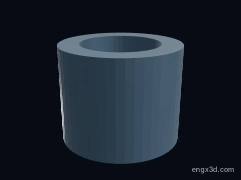
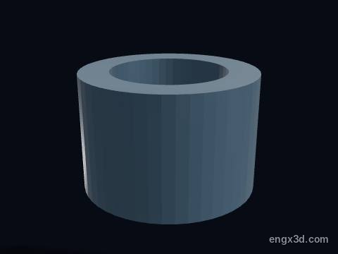
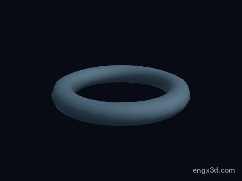
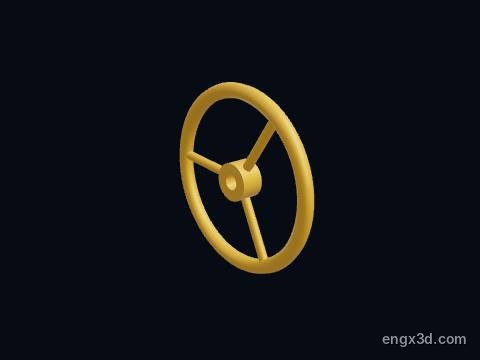
Every part with a picture, what it does and its own STL file: disc, stem, disc pin, valve body, seat liner, upper stem bushing, lower stem bushing, stem o-ring and more. Open any part in the live 3D atlas to see where it sits and how it moves. A part used several times (valves, bolts) is shown once with its count.
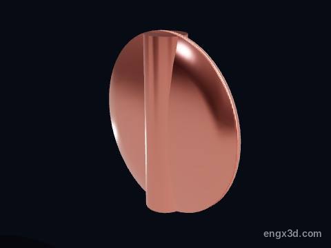
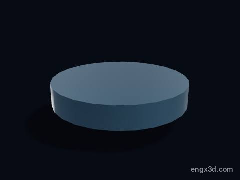
The disc is the round plate that turns a quarter turn inside the bore to open or shut the butterfly valve. Edge-on to the flow it is fully open; turned square across the pipe its edge seals against the rubber seat. It stays in the flow even when open, which is why a butterfly valve loses a little more pressure than a full-bore gate valve.
More about this part
Fully open this 6-inch valve passes about Cv 2790 (Kv 2413).
Concentric (zero offset) means the stem runs through the centre of the disc and the pipe; double and triple offset valves move the stem behind the seat so the disc lifts away instead of rubbing.
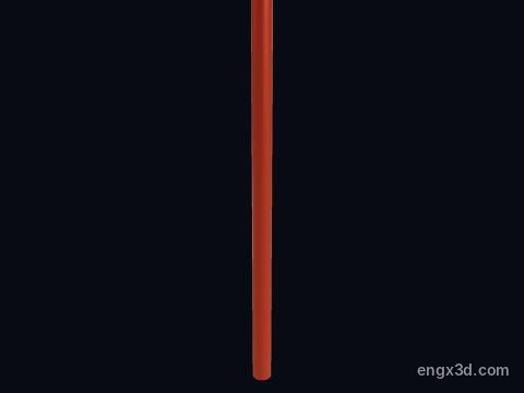
The stem (shaft) is the Ø19.1 mm stainless rod that passes through the disc and turns it. Its top end is driven by the worm wheel of the gear operator; it turns but never rises, which is why butterfly valves are called quarter-turn valves.
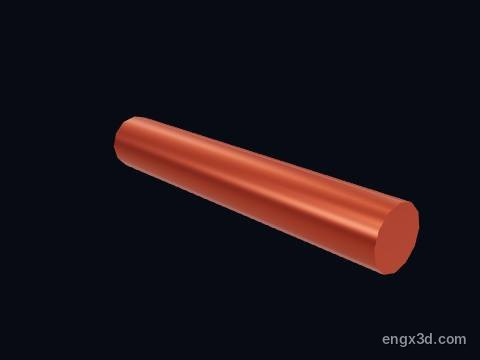
A disc pin locks the disc to the stem so the two turn together. Pins, splines or a square drive are all used; a sheared pin leaves the handwheel turning while the disc stays still.
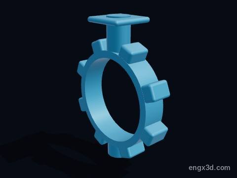
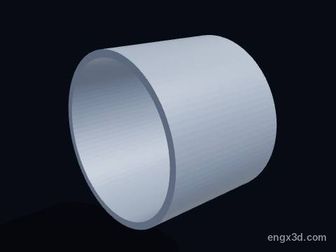
The valve body is the short ductile-iron ring that sits between two pipe flanges and holds the seat, disc and stem. This lug body is only 56 mm thick face to face, and its eight tapped lugs line up with the 8 bolts of an NPS 6 Class 150 flange.
More about this part
Lug bodies let the downstream pipe be removed while the valve still holds pressure on the upstream side (dead-end service); a wafer body is simply clamped between the flanges.
Drawn see-through so the disc and seat stay visible.
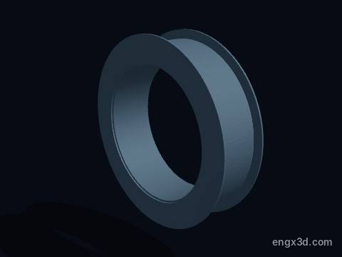
The seat is the rubber liner inside the body. The edge of the disc presses into it to shut the valve, and its moulded lips on both faces also act as the gaskets against the pipe flanges, so no separate flange gaskets are used.
More about this part
In a concentric valve the disc edge rubs the seat every time it opens and closes, so the seat is the part that wears; EPDM suits water, NBR suits oils.
Resilient seats limit this design to low pressure and temperature, about 120 °C.
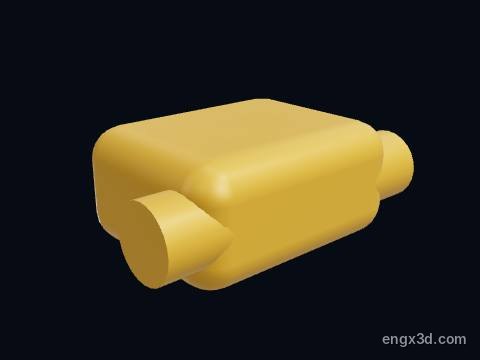
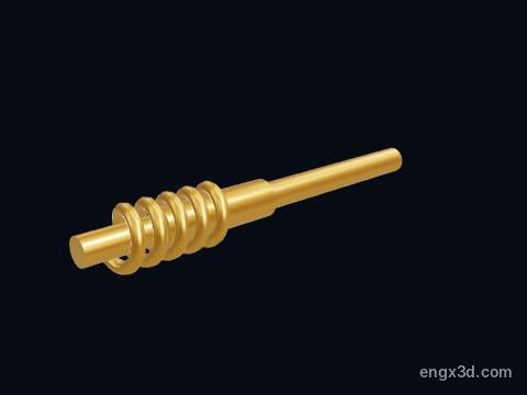
The gearbox housing of the worm gear operator holds the worm and the worm wheel. A 24 : 1 reduction means 6 handwheel turns move the disc through its 90°, which keeps the handwheel force low and stops the line pressure from turning the disc on its own.
More about this part
A worm drive is self-locking: the disc cannot back-drive the handwheel, so the valve holds any position for throttling.
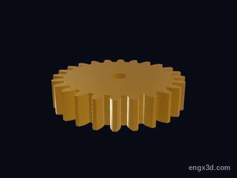
The worm wheel sits on the top of the valve stem inside the gear operator. The worm turns it 24 times slower than the handwheel, and it turns the stem and disc through 90° between the two travel stops.
More about this part
Only about a quarter of its teeth are ever used, so many operators use a quadrant (a 90° segment) instead of a full wheel.
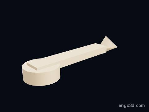
A travel stop screw sets the end of the disc's quarter turn. One sets the fully shut position, so the disc presses into the seat just enough to seal; the other sets fully open.
More about this part
Over-closing a resilient-seated valve past its stop crushes the seat and makes the valve harder to open.
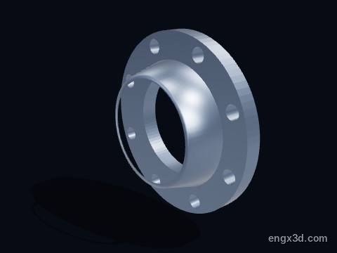
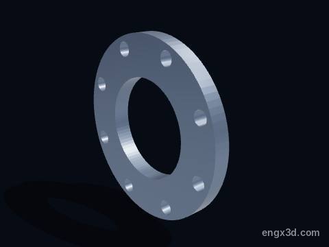
A pipe flange is the weld-neck flange on the end of the pipe that bolts to the valve. This NPS 6 Class 150 flange (ASME B16.5) is Ø279.4 mm with 8 bolt holes on a Ø241.3 mm circle.
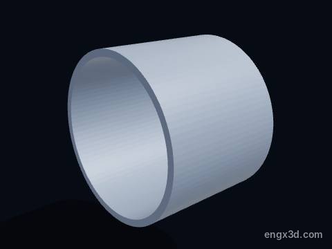
A short length of NPS 6 pipe, Ø168.3 mm outside, welded to its flange on each side of the valve.
More about this part
The disc swings into the pipe when it opens, so the pipe and any nearby fittings must leave it room; it should not sit right against an elbow or a check valve.
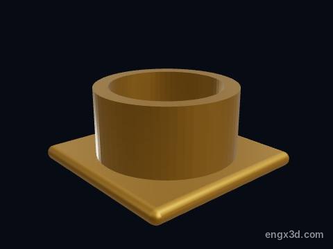
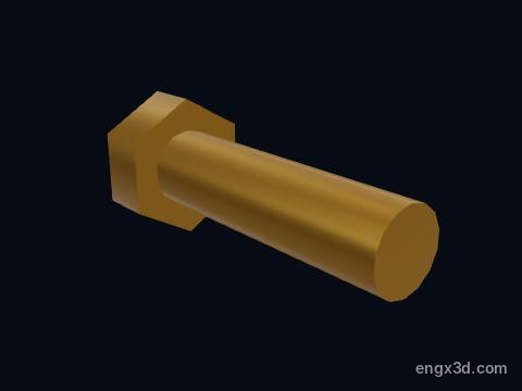
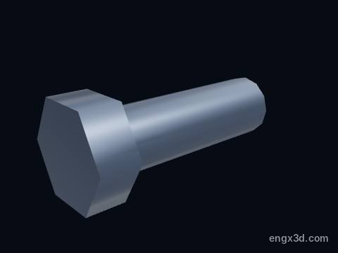
A flange bolt clamps the pipe flange to the threaded lug of the valve body. With a lug body each flange has its own set of bolts, so either side can be unbolted on its own.
More about this part
Tighten in a star pattern; over-tightening squeezes the rubber seat lips and can make the disc stiff to turn.
A pipe flange is the weld-neck flange on the end of the pipe that bolts to the valve. This NPS 6 Class 150 flange (ASME B16.5) is Ø279.4 mm with 8 bolt holes on a Ø241.3 mm circle.
A short length of NPS 6 pipe, Ø168.3 mm outside, welded to its flange on each side of the valve.
More about this part
The disc swings into the pipe when it opens, so the pipe and any nearby fittings must leave it room; it should not sit right against an elbow or a check valve.
Yes. The butterfly valve 3D model is free for personal and educational use under CC BY-NC 4.0: credit "Engine-X by Parth Parmar (engx3d.com)". Selling the files or prints, or other commercial use, needs written permission.
Which file formats is the butterfly valve 3D model in?
GLB (glTF 2.0) with colours and named parts, STL in millimetres (Z-up) for CAD, slicers and 3D printing, USDZ for AR on iPhone, and a ZIP with all 21 parts as separate STL files.
How many parts does the butterfly valve 3D model have?
38 named pieces in 4 systems (disc & stem, body & seat, gear operator, flanges & pipe). Repeated pieces such as bolts are folded together, which leaves 21 different parts, each one downloadable on its own.
Can I 3D print the butterfly valve model?
Yes, download the STL (whole machine or single parts) and open it in your slicer. It is a learning model at real scale, not a print kit: some parts touch or overlap and there are no fit tolerances, so scale it and print parts one by one.
How do I see the butterfly valve in AR on my phone?
Tap "View in your room" on this page. Android opens Google Scene Viewer and iPhone opens AR Quick Look, both without an app, and you can place the model at real size on the floor or a table.
Can I see the butterfly valve working in 3D?
Yes. Tap "Play live 3D here" or open the Engine-X atlas (engx3d.com/atlas#m=butterflyvalve): it runs in the browser with true motion, and you can explode it, cut it open and X-ray it.
How to credit or cite this model
Credit line: Butterfly valve 3D model, Engine-X by Parth Parmar (engx3d.com)
Citation: Parmar, P. (2026). Butterfly valve 3D model [3D model, CC BY-NC 4.0]. Engine-X. https://engx3d.com/3d-models/butterfly-valve
Used this model?
For a class, a project, a print or a video? Tell us how it went. With your OK, we may feature your work here.
 Open full screen →
 View in your room · AR